RSB-3810_Android_User_Guide
產品介紹(Product introduction )
產品特性(Product Features)
- MediaTek Genio 1200 4核心A78和4核心A55
- 內建LPDDR4 8GB,4000MT/s記憶體
- HDMI 4k60fps,1 x 雙通道24位元LVDS
- 1 x 4線RS-232/422/485,2 x USB3.2 Gen1 By 1,2 x USB2.0,1 x Micro SD,1 x Mic. in / Line out
- 1 x M.2 3052 Key B for 5G,1 x M.2 2230 Key E Slot for WiFi/BT
- 支援UIO40-Express I/O板擴充
- 支援Ubuntu、Ycoto Linux和Android
產品官網連結(Product official website link)
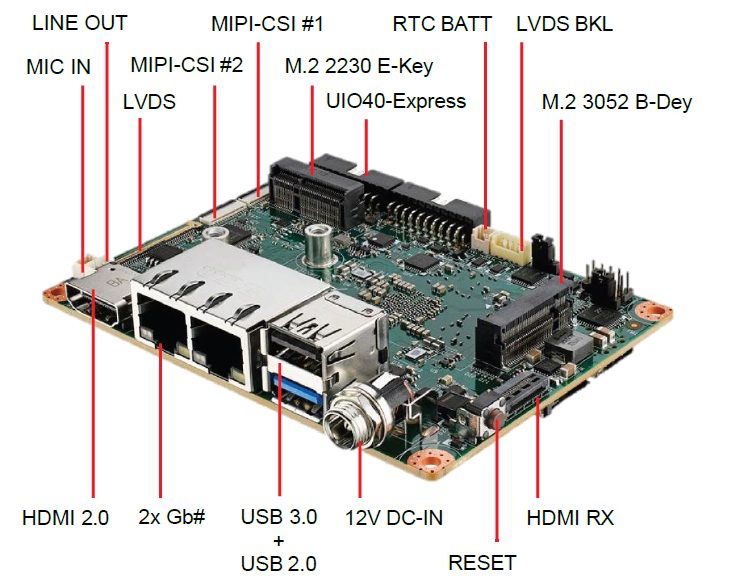
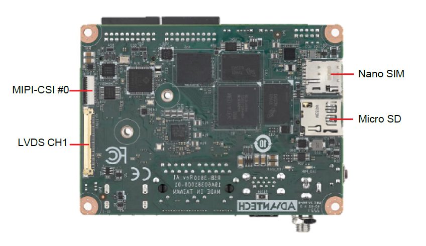
硬件接口說明(Hardware interface introduction)
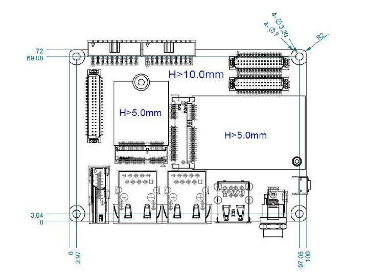
接口布局和尺寸(Layout and Sizes)
RSB-3810 接口布局圖 Board Dimension Layout
[ ]
]
[ ]
]
Jumper list:
| BL0 | Backlight Power Select for LVDS0 (Default 5V) |
| VDD0 | LVDS VDD (Default 3.3V) |
Connectot list:
| BAT | RTC Battery CONN |
| BL0 | LVDS Backlight |
| COM1 | Debug Console + RS232/RS485 |
| CSI0 | MIPI-CSI Camera Input 0 |
| CSI1 | MIPI-CSI Camera Input 1 |
| CSI2 | MIPI-CSI Camera Input 2 |
| DCIN/DCIN1 | 12V DC Power Input by DC Jack/ by Pin Header |
| HDMI | HDMI CONN |
| LVDS0 | LVDS Channel 0 CONN |
| LVDS1 | LVDS Channel 1 CONN |
| M2 | M.2 Key E CONN |
| MIC | MIC In Pin Header |
| M2B | M.2 Key B CONN |
| RST | Reset Button |
| SD | SD Slot |
| SIM | SIM Slot |
| UIO1 | UIO40-Express Pin Header 1 |
| UIO2 | UIO40-Express Pin Header 2 |
| USB1 | USB CONN. (USB 3.2 Gen 1 on TOP + USB 2.0 on BOT) |
| DL_KEY | Download Key |
接口引脚定義 (Pin definitions)
- BAT (RTC Battery CONN.)
- BL1 (LVDS Backlight 1)
- COM1 (Debug Console + RS232/RS485)
- CSI0 (MIPI-CSI Camera Input 0)
- CSI1 (MIPI-CSI Camera Input 1)
- CSI2 (MIPI-CSI Camera Input 2)
- DCIN (12V DC Jack)
- DCIN1 (12V DC-IN Pin Header)
- HDMI (HDMI CONN.)
- LAN (Ethernet eth0+eth1)
- LOUT (Line Out Pin Header)
- LVDS0 (LVDS channel 0)
- LVDS1 (LVDS channel 1)
- M2 (M.2 Key E CONN.)
- MIC (MIC In Pin Header)
- M2B (M.2 keyB CONN.)
- RST (Reset Button)
- SD (SD Slot)
- SIM (SIM Slot)
- UIO1 (UIO40-Express Pin Header 1)
- UIO2 (UIO40-Express Pin Header 2)
- USB 1 (USB 3.2 Gen 1 on TOP + USB 2.0 on BOT)
- DL_KEY(Download Key)
- LED
**机械尺寸 (**Mechanical Characteristics)
[ ]
]
快速入门 (Quick Start)
系统下载 (OS Download)
Android 11 OS download
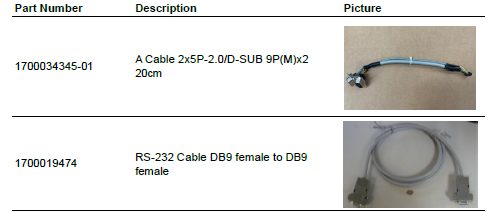
Debug port 連接與設定(Debug Port Connection and Setting)
- RSB-3810 debug port is shared with COM1. Please connect the debug console cable 1700034345-01 & 1700019474. Then connect the USB-to-RS232 Cable to your PC terminal. Connect the cable to COM1 pin header to the nearby the HDMI connector.
[ ]
2. RSB-3810 can communicate with a host server using serial cables. Common serial communication programs such as HyperTerminal, Tera Term or PuTTY can be used in such applications. The example demonstrated below describes the serial terminal setup using Tera Term on a Windows host: Open Tera Term on your Windows PC, set the Baud rate to 921600.
]
2. RSB-3810 can communicate with a host server using serial cables. Common serial communication programs such as HyperTerminal, Tera Term or PuTTY can be used in such applications. The example demonstrated below describes the serial terminal setup using Tera Term on a Windows host: Open Tera Term on your Windows PC, set the Baud rate to 921600.
燒錄方法 (Flash eMMC Method)
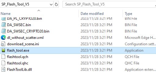
Step1: 下載MTK燒錄工具SP Flash Tool V5 (Download MTK flash tool "SP Flash Tool V5")
支援作業系統(Support OS):
- Windows 7
- Windows 10
- Ubuntu 16.x
- Ubuntu 18.x
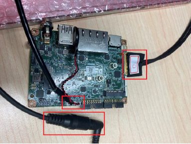
Step2:使用USB Type-A to Type-A線連接電腦處機與裝置的USB Type-A孔位, 如下圖位置(Connect the usb type A to host computer and device type A port)
[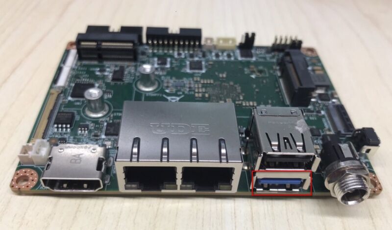 ]
]
Step3: 重BSP下載以下image檔案或是解壓縮image檔(You need to download the image files from BSP as below or extract from image file.)
BSP image File path:out/target/product/mt8395_rsb3810a1
MT8195_Android_scatter.txt
preloader_mt8395_rsb3810a1.bin
vbmeta.img
vbmeta_system.img
vbmeta_vendor.img
spmfw.img
pi_img.img
dpm.img
scp.img
sspm.img
mcupm.img
cam_vpu1.img
cam_vpu2.img
cam_vpu3.img
lk.img
boot.img
dtbo.img
tee.img
logo.bin
super.img
userdata.img
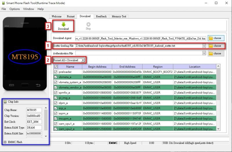
Step 4: 執行SP flash tool V5 燒錄工具(Launch SP flash tool V5)
[ ]
]
(1) 選擇MT8195_Android_scatter.txt檔(Select the MT8195_Android_scatter.txt file)
(2)選擇"Format ALL + Download"(Select theFormat All + Download)
(3)點選Download按鈕(Click the Downloadbutton)
[ ]
]
Step 5 . 重新啟動裝置後系統會自己開始燒錄(Reboot the device and start to burn all image)
[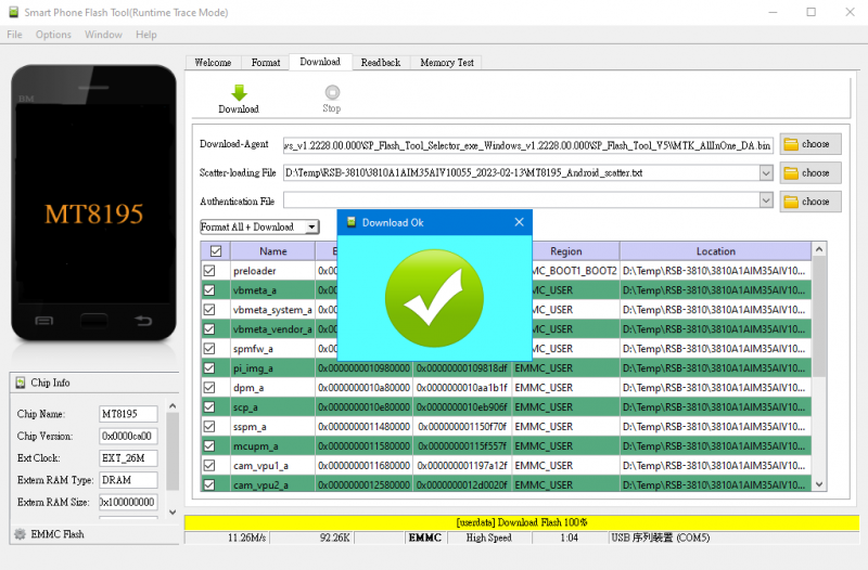 ]
Step 6. 重新上電開機 (Turn on the power, then check the Debug message)
]
Step 6. 重新上電開機 (Turn on the power, then check the Debug message)
Android系统的基本使用(Android System Basic Operating Method)
Display Setting (RSB-3810)
HDMI TX:
Step 1: Setting-->Storage
Step 2: Play a video
CHeck HDMI mode and support resolution:
cat /sys/class/graphics/fb0/modes
cat /sys/class/drm/card0-HDMI-A-1/status
cat /sys/class/drm/card0-HDMI-A-1/modes
HDMI RX:
(1) Connect a play video host PC device
(2) connect HDMI from PC to RSB-3810
[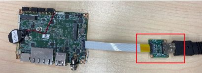 ]
(3) setenforce 0
]
(3) setenforce 0
(4) open the RxVideo apk
[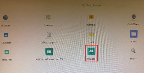 ]
(5) Play a video on host PC
]
(5) Play a video on host PC
(6) check the video and sound can output to HDMI monitor
LVDS: Dual Channel LVDS Panel: G215HVN0 (VDD: 5V, Backlight Power: 12V)
Step 1: Connect 96LEDK-A215FH30NF2 LVDS panel with the LVDS cable. Connect this to the LVDS. Connect the Backlight cable to BL1.
Step 2: Connect another 12V adapter to the DC-Jack on the backlight cable.
Step 3: Power on RSB-3810 and the extra 12V adapter.
Step 4: Press enter after boot. The system will stop at u-boot as demonstrated below, enter the command in red and press enter
[ ]
]
Audio使用方法(Audio Testing Method):
Step 1: Check audio codec
console:/ # cat /proc/asound/cards
0 [mt63xxaccdet ]: mt63xx-accdet - mt63xx-accdet
mt63xx-accdet
1 [mt8195sound ]: mt8195-sound - mt8195-sound
mt8195-sound
Step 2: Record and playback:
Play audio file and check the sound output from Linu-out. Copy LRMonoPhase4.wav to the system
stop audioserver
tinymix -D 1 'O176 I000 Switch' 1
tinymix -D 1 'O177 I001 Switch' 1
tinymix -D 1 'DAC In Mux' 'Normal Path'
tinymix -D 1 'HP Mux' 'Audio Playback'
tinyplay /storage/self/primary/LRMonoPhase4.wav -D 1 -d 2 -p 1024 -n 2
Connect Audio output from phone to RSB-3810 MIC. Record audio from phone and play the recorded file to check the sound.
stop audioserver
tinymix -D 1 'O040 I168 Switch' 1
tinymix -D 1 'O041 I169 Switch' 1
tinymix -D 1 'MISO0_MUX' UL1_CH1
tinymix -D 1 'MISO1_MUX' UL1_CH1
tinymix -D 1 'ADC_L_Mux' 'Left Preamplifier'
tinymix -D 1 'PGA_L_Mux' 'AIN1'
tinycap /data/rec.wav -D 1 -d 8 -r 48000 -c 2 -b 32 -T 10
tinyplay /data/rec.wav -D 1 -d 2 -p 1024 -n 2
M.2使用方法EWM-W174(M.2 Testing Method with EWM-W174):
- Test Wi-Fi with EWM-W174M201E Module (PCIe Interface)
Step 1: Open Android Setting.
Step 2: Click Network & internet.
Step 3: Search for WIFI
[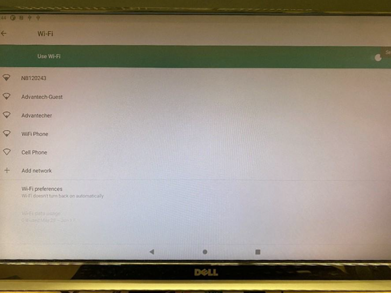 ]
]
- Test Bluetooth with EWM-W174M201E Module (USB Interface)
Step 1: Open Android Setting.
Step 2: Click Connected devices.
Step 3: Click Connection preferences.
Step 4: Click Bluetooth.
Step 5: On and Pair new device
Step 6: Available devices
Serial port使用方法(Serial port Testing Method):
- RS-232 Loopback Test (eg. ttyS3):
stty -F /dev/ttyS3 speed 115200 ignbrk -brkint -icrnl -imaxbel - opost -onlcr -isig -icanon -iexten -echo -echoe -echok -echoctl - echoke
cat /dev/ttyS3 &
echo "Serial Test" > /dev/ttyS3
- RS-422 Test:
Step 1: First change the debug console port to UART2 (UIO-4030COM_3), or use telnet to login to the system console to issue the command for the com port test.
Step 2: Test RS-422 with Adam-4520. Connect Adam-4520 with COM1 with 1700100250 DB9 as the following:
Adam-4520 RX- RSB-3810 COM1 DB9 Pin 1,
Adam-4520 RX+ RSB-3810 COM1 DB9 Pin 2,
Adam-4520 TX- RSB-3810 COM1 DB9 Pin 4,
Adam-4520 TX+ RSB-3810 COM1 DB9 Pin 3,
Step 3: Set GPIO#328, GPIO#327 Set to 1,1
echo 328 > /sys/class/gpio/export
echo 327 > /sys/class/gpio/export# echo out
out > /sys/class/ gpio/gpio328/direction
echo out > /sys/class/gpio/gpio327/direction
echo 1 > /sys/class/gpio/gpio328/value
echo 1 > /sys/class/gpio/gpio327/value
Step 4: Test RS-422 with Adam-4520. Connect Adam-4520 with COM1 with 1700100250 DB9 as the following command:
stty -F /dev/ttyS2 speed 115200 ignbrk -brkint -icrnl -imaxbel - opost -onlcr -isig -icanon -iexten -echo -echoe -echok -echoctl - echoke
cat /dev/ttyS2 &
echo "Serial Test" > /dev/ttyS2
- RS-485 Test:
Step 1: Test RS-485 with Adam-4520. Connect Adam-4520 with COM1 with 1700100250 DB9 as the following:
Adam-4520 Pin 1: Data- connect to DB9 Pin 1: COM_DCD.
Adam-4520 Pin 2: Data+ connect to DB9 Pin 3: COM_RXD.
Step 2: Set GPIO#328, GPIO#327 Set to 0,1
echo 328 > /sys/class/gpio/export
echo 327 > /sys/class/gpio/export# echo out
out > /sys/class/ gpio/gpio328/direction
echo out > /sys/class/gpio/gpio327/direction
echo 0 > /sys/class/gpio/gpio328/value
echo 1 > /sys/class/gpio/gpio327/value
Step 3: Test RS-422 with Adam-4520. Connect Adam-4520 with COM1 with 1700100250 DB9 as the following command:
$ stty -F /dev/ttyS2 -echo -onlcr 921600 raw
$ cat /dev/ttyS2 &
$ echo "Serial Port Test" > /dev/ttyS2
or
$ microcom -s 921600 -X /dev/ttyS2
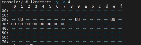
I2C使用方法(I2C Test Method):
Step 1: Check i2c device
[ ]
]
Step 2: I2c set and get
console:/ # i2cdetect -y -a 4
USB: USB disk test (USB 2.0/ USB 3.2 Gen 1 By 1 port)
Step 1: Issue the following command (lsusb -t) after inserting a USB disk into the USB 2.0 port or USB 3.2 Gen 1 port to check if the USB device is listed.
lsusb -t
Step 2: Test (eg. if usb disk is /dev/sda)
dd if=/dev/urandom of=data bs=1 count=1024
dd if=/dev/sda of=backup bs=1 count=1024 skip=4096 # dd if=data of=/dev/sda bs=1 seek=4096
dd if=/dev/sda of=data1 bs=1 count=1024 skip=4096 # diff data data1
dd if=backup of=/dev/sda bs=1 seek=4096
RTC使用方法(RTC Test Method):
Step 1: Set system time to current, then write to RTC
console:/ # date 041610362025 && hwclock -w && date
Step 2: Set one incorrect time, then read time from RTC to verify
console:/ # date 113009362023 && hwclock -r
Step 3: Restore the RTC time to system time
console:/ # date && hwclock –s
Step 4: Check the system and RTC time
console:/ # date && hwclock -r
eMMC/SD/SPI flash使用方法(eMMC/SD/SPI flash Testing Method):
eMMC: /dev/mmcblk2
SD: /dev/ mmcblk1p1
Test (eg. emmc)
Step 1: Open Android Setting.
Step 2: Click Storage
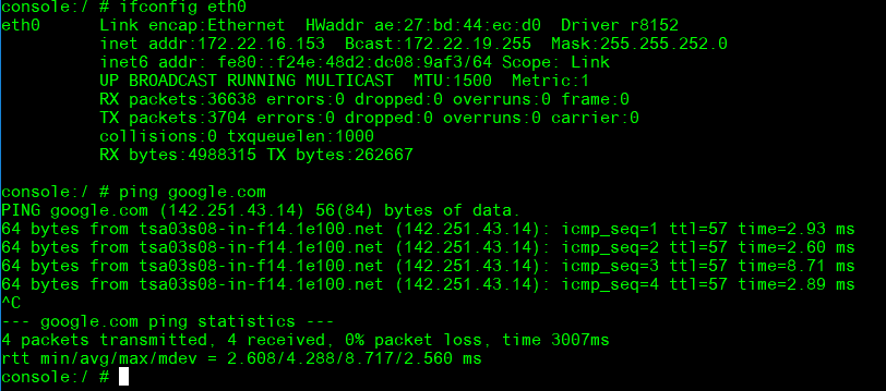
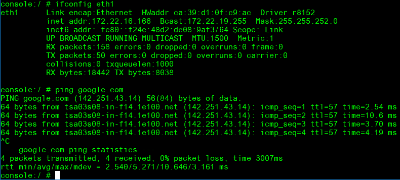
Ethernet使用方法(Ethernet Testing Method):
Step 1: Check the Ethernet device
ifconfig
Step 2: Connect the cable and ping test (eg. Eth0)
ping 8.8.8.8
[ ]
[
]
[ ]
]
GPIO使用方法(GPIO Testing Method):
- GPIO Pins:
UIO Extension 1(UIO1):
| Pin | Numbers |
| GPIO2 | 315 |
| GPIO4 | 316 |
UIO Extension2 (UIO2):
| Pin | Numbers |
| GPIO5 | 317 |
| GPIO6 | 318 |
| GPIO7 | 319 |
| GPIO8 | 320 |
| GPIO9 | 321 |
| GPIO10 | 322 |
| GPIO11 | 323 or 408 |
| GPIO12 | 324 or 409 |
- GPIO Loopback Test (Using GPIO2 and GPIO4 as examples):
Step 1: Connect GPIO2 and GPIO4
Step 2: Export GPIO interface
echo 315 > /sys/class/gpio/export
echo 316 > /sys/class/gpio/export
Step 3: Set GPIO direction
echo out > /sys/class/gpio/gpio1/direction
echo in > /sys/class/gpio/gpio2/direction
Step 4: Read value and set output value than check
cat /sys/class/gpio/gpio2/value 0
echo 1 > /sys/class/gpio/gpio1/value
cat /sys/class/gpio/gpio2/value
1
Watchdog使用方法(Watchdog Testing Method):
- Internal Watchdog:
Step 1: System will reboot after 60 sec. androidboot.bootreason=HW_reboot
stop watchdogd
Step 2: System will reboot after 60 sec. androidboot.bootreason=HW_reboot
stop watchdogd && echo 1 > /dev/watchdog
Step 3: System will reboot after 3 sec. androidboot.bootreason=reboot
reboot
Step 4: System will reboot after 1 sec. androidboot.bootreason=kernel_panic
echo c > /proc/sysrq-trigger
- External Watchdog:
Step 1: System will reboot after 60 sec. androidboot.bootreason=usb
echo 1 > /dev/watchdog1
Step 2: System will not reboot. Watchdog can be refreshed when feed dog before it timeout.
Step 3: System will reboot after 10 sec ==> Watchdog does not refresh after it time- out.
ext_wdt_driver_test 10 1 0
androidboot.bootreason=usb
ext_wdt_driver_test 10 1 0 && Ctrl + C
Camera(Default MIPI-CSI0 and MIPI-CSI1 are for Sony IMX214):
MIPI-CSI0 (Tested with IMX214 + mini-SAS to MIPI-CSI Cable)
Step 1: Use Android camera app to test
Step 2: Take pictures
Step 3: Video recording
Step 4: Check photo
MIPI-CSI1 (Tested with IMX214 + mini-SAS to MIPI-CSI Cable)
Step 1: Use Android camera app to test
Step 2: Take pictures
Step 3: Video recording
Step 4: Check photo
MIPI-CSI2 (Tested with IMX214 + mini-SAS to MIPI-CSI Cable)
Step 1: Remove the CSI-0 and CSI-1 camera first
Step 2: Use Android camera app to test
Step 3: Take pictures
Step 4: Video recording
Step 5: Check photo
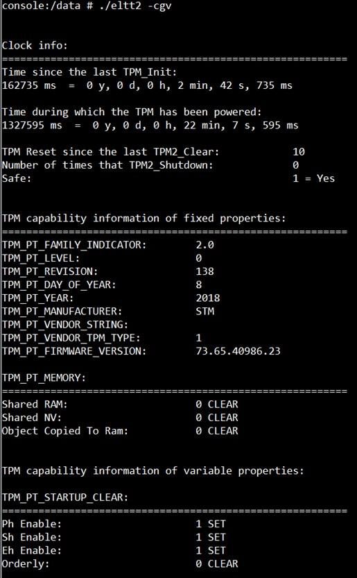
TPM測試方法(TPM Testing Method):
Please use tpm_test.bin to test.
eltt2 -cgv
[ ]
]
LED ON/OFF 使用方法(LED ONOFF Testing Method):
LED Status: Detect gpio signal LED ON: echo 255 >
/sys/class/leds/user/brightness LED OFF: echo 0 >
/sys/class/leds/user/brightness
UIO-4030使用方法(UIO-4030 Testing Method):
| 1 | UART(COM_3) | # stty -F /dev/ttyS3 -echo -onlcr 921600 raw # cat /dev/ttyS3 & # echo "Serial Port Test" > /dev/ttyS3 or #microcom -s 921600 -X /dev/ttyS3 |
| 2 | GPIO | 4 DI & 4 DO Pins (UIO Extension_UIO2) input pin#5: gpio 317 output pin#6: gpio 318 input pin#7: gpio 319 output pin#8: gpio 320 input pin#9: gpio 321 output pin#10: gpio 322 input pin#11: gpio 323 output pin#12: gpio 324 (Note: gpio 323 & gpio 324 need to set the gpio 345 to high) |
| 3 | RS-485(COM_4) | Test RS-485 with Adam-4520. Adam-4520 Pin Data- and Pin Data+ connect to UIO-4030 COM_4 Pin 1 and Pin 2. # stty -F /dev/ttyUSB0 speed 115200 ignbrk -brkint -icrnl - imaxbel -opost -onlcr -isig -icanon -iexten -echo -echoe -echok -echoctl -echoke # cat /dev/ttyUSB0 & # echo "Serial Test" > /dev/ttyUSB0 |
| 4 | EEPROM | # echo -n $'\x06\x05\x04\x03\x02\x01' > /data/test1 # dd if=/data/test1 of=/sys/bus/i2c/devices/3-0050/eeprom # dd if=/sys/bus/i2c/devices/3-0050/eeprom of=/data/test2 conv=fsync |
UIO-4032使用方法(UIO-4032 Testing Method):
| 1 | UART COM_3:ttyS3 COM_4:ttyS1 | # stty -F /dev/ttyS3 -echo -onlcr 921600 raw # cat /dev/ttyS3 & # echo "Serial Port Test" > /dev/ttyS3 or # microcom -s 921600 -X /dev/ttyS3 # cat /dev/ttyS3 & |
| # stty -F /dev/ttyS1 -echo -onlcr 921600 raw # cat /dev/ttyS1 & # echo "Serial Port Test" > /dev/ttyS1 or # microcom -s 921600 -X /dev/ttyS1 | ||
| 2 | USB | USB disk write/read/verify pattern |
| 3 | Ethernet | # ifconfig # ping 8.8.8.8 |
| 4 | EEPROM | # echo -n $'\x06\x05\x04\x03\x02\x01' > /data/test1 # dd if=/data/test1 of=/sys/bus/i2c/devices/3-0050/eeprom # dd if=/sys/bus/i2c/devices/3-0050/eeprom of=/data/test2 conv=fsync |
UIO-4034使用方法(UIO-4034 Testing Method):
| 1 | UART COM_3:ttyS3 COM_4:ttyS1 | $ stty -F /dev/ttyS3 -echo -onlcr 921600 raw $ cat /dev/ttyS3 & $ echo "Serial Port Test" > /dev/ttyS3 or $ microcom -s 921600 -X /dev/ttyS3 |
| $ stty -F /dev/ttyS1 -echo -onlcr 921600 raw $ cat /dev/ttyS1 & $ echo "Serial Port Test" > /dev/ttyS1 or $ microcom -s 921600 -X /dev/ttyS1 | ||
| 2 | CAN Bus | 1. ip link set can0 up type can bitrate 125000 # ifconfig can0 up # ip link set can1 up type can bitrate 125000 # ifconfig can1 up 1. candump can0 & # cansend can1 1F334455#1122334455667788 |
| 3 | EEPROM | # echo -n $'\x06\x05\x04\x03\x02\x01' > /data/test1 # dd if=/data/test1 of=/sys/bus/i2c/devices/3-0050/eeprom # dd if=/sys/bus/i2c/devices/3-0050/eeprom of=/data/test2 conv=fsync |
UIO-4036使用方法(UIO-4036 Testing Method):
| 1 | LAN Switch | # ifconfig # ping 8.8.8.8 |
| 2 | EEPROM | # echo -n $'\x06\x05\x04\x03\x02\x01' > /data/test1 # dd if=/data/test1 of=/sys/bus/i2c/devices/3-0050/eeprom # dd if=/sys/bus/i2c/devices/3-0050/eeprom of=/data/test2 conv=fsync |
UIO-4038使用方法(UIO-4038 Testing Method):
| 1 | LAN0(WAN) | # ifconfig |
| 2 | LAN | # ping 192.168.100.1 |
| 3 | EEPROM | # echo -n $'\x06\x05\x04\x03\x02\x01' > /data/test1 # dd if=/data/test1 of=/sys/bus/i2c/devices/3-0050/eeprom # dd if=/sys/bus/i2c/devices/3-0050/eeprom of=/data/test2 conv=fsync |
UIO-4040使用方法(UIO-4040 Testing Method):
| 1 | SSD | 1. SSD disk write/read/verify pattern Disk /dev/sda: 119.24 GiB, 128035676160 bytes, 250069680 sectors Disk model: UIO-4040 Units: sectors of 1 * 512 = 512 bytes Sector size (logical/physical): 512 bytes / 512 bytes I/O size (minimum/optimal): 512 bytes / 512 bytes |
| 2 | EEPROM | # echo -n $'\x06\x05\x04\x03\x02\x01' > /data/test1 # dd if=/data/test1 of=/sys/bus/i2c/devices/3-0050/eeprom # dd if=/sys/bus/i2c/devices/3-0050/eeprom of=/data/test2 conv=fsync |
通用方法(General Method)
ADB debug:
Step1 :RSB-3810 Device setting
console:/ $ su
console:/ # setprop service.adb.tcp.port 5555
console:/ # stop adbd
console:/ # start adbd
console:/ # ifconfig
Step2 : adb platform-tools
D:\platform-tools>ping 172.22.28.102
D:\platform-tools>adb connect 172.22.28.102:5555
D:\platform-tools>adb root
D:\platform-tools>adb shell