RSB-3810 user guide Ubuntu22.04
Contents
- 1產品介紹(Product introduction ) 1.1產品特性(Product Features) 1.2產品官網連結(Product official website link)
- 2硬件接口說明(Hardware interface introduction) 2.1接口布局和尺寸(Layout and Sizes) 2.2RSB-3810 接口布局圖 Board Dimension Layout 2.3接口引脚定義 (Pin definitions) 2.4机械尺寸 (Mechanical Characteristics)
- 3快速入门 (Quick Start) 3.1系统下载 (OS Download) 3.2Debug port 連接與設定(Debug Port Connection and Setting) 3.3燒錄方法 (Flash eMMC Method)
- 4Linux系统的基本使用(Linux System Basic Operating Method) 4.1I2C Setting (RSB-3810) 4.2Display Setting (RSB-3810) 4.3Audio使用方法(Audio Testing Method): 4.4M.2使用方法(M.2 Testing Method): 4.5Serial port使用方法(Serial port Testing Method): 4.6I2C使用方法(I2C Test Method): 4.7USB: USB disk test (USB 2.0/ USB 3.2 Gen 1 By 1 port) 4.8RTC使用方法(RTC Test Method): 4.9eMMC/SD/SPI flash使用方法(eMMC/SD/SPI flash Testing Method): 4.10Ethernet使用方法(Ethernet Testing Method): 4.11GPIO使用方法(GPIO Testing Method): 4.12Watchdog使用方法(Watchdog Testing Method): 4.13LED ON/OFF 使用方法(LED ONOFF Testing Method): 4.14UIO-4030使用方法(UIO-4030 Testing Method): 4.15UIO-4032使用方法(UIO-4032 Testing Method): 4.16UIO-4034使用方法(UIO-4034 Testing Method): 4.17UIO-4036使用方法(UIO-4036 Testing Method): 4.18UIO-4038使用方法(UIO-4038 Testing Method): 4.19UIO-4040使用方法(UIO-4040 Testing Method): 4.20安裝AI SDK使用方法(Install AI SDK):
- 5通用方法(General Method) 5.1讀取溫度(Read Thermal):
- 6ToolChain
- 7BSP編譯方法(BSP Compile Method)
產品介紹(Product introduction )
產品特性(Product Features)
- MediaTek Genio 1200 4核心A78和4核心A55
- 內建LPDDR4 8GB,4000MT/s記憶體
- HDMI 4k60fps,1 x 雙通道24位元LVDS
- 1 x 4線RS-232/422/485,2 x USB3.2 Gen1 By 1,2 x USB2.0,1 x Micro SD,1 x Mic. in / Line out
- 1 x M.2 3052 Key B for 5G,1 x M.2 2230 Key E Slot for WiFi/BT
- 支援UIO40-Express I/O板擴充
- 支援Ubuntu Linux和Android
產品官網連結(Product official website link)
硬件接口說明(Hardware interface introduction)
接口布局和尺寸(Layout and Sizes)
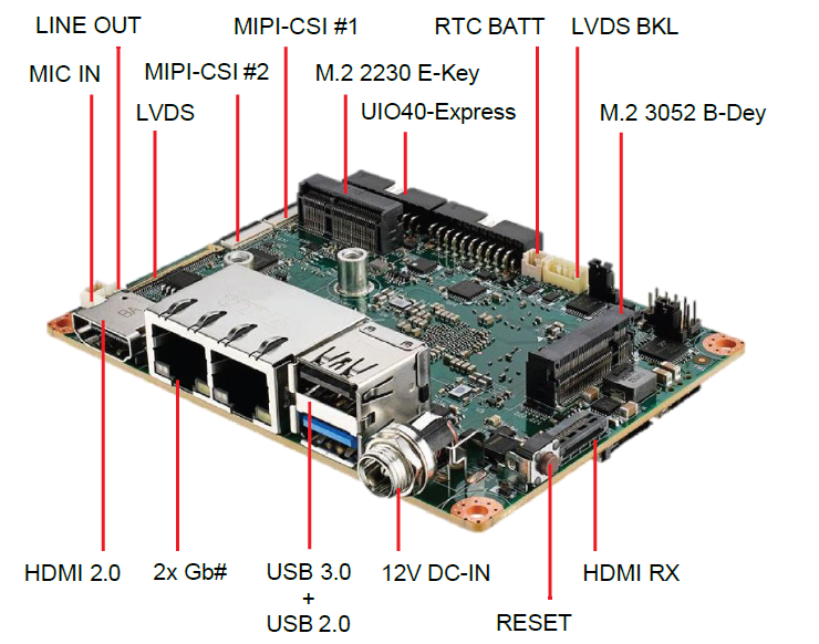
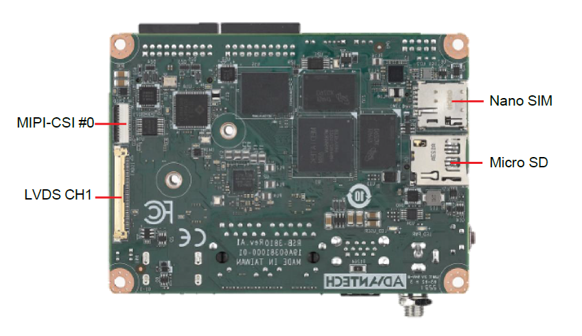
RSB-3810 接口布局圖 Board Dimension Layout
Jumper list:
| BL0 | Backlight Power Select for LVDS0 (Default 5V) |
|---|---|
| VDD0 | LVDS VDD (Default 3.3V) |
Connectot list:
| BAT | RTC Battery CONN |
|---|---|
| BL0 | LVDS Backlight |
| COM1 | Debug Console + RS232/RS485 |
| CSI0 | MIPI-CSI Camera Input 0 |
| CSI1 | MIPI-CSI Camera Input 1 |
| CSI2 | MIPI-CSI Camera Input 2 |
| DCIN/DCIN1 | 12V DC Power Input by DC Jack/ by Pin Header |
| HDMI | HDMI CONN |
| LVDS0 | LVDS Channel 0 CONN |
| LVDS1 | LVDS Channel 1 CONN |
| M2 | M.2 Key E CONN |
| MIC | MIC In Pin Header |
| M2B | M.2 Key B CONN |
| RST | Reset Button |
| SD | SD Slot |
| SIM | SIM Slot |
| UIO1 | UIO40-Express Pin Header 1 |
| UIO2 | UIO40-Express Pin Header 2 |
| USB1 | USB CONN. (USB 3.2 Gen 1 on TOP + USB 2.0 on BOT) |
| DL_KEY | Download Key |
接口引脚定義 (Pin definitions)
- BAT (RTC Battery CONN.)
- BL1 (LVDS Backlight 1)
- COM1 (Debug Console + RS232/RS485)
- CSI0 (MIPI-CSI Camera Input 0)
- CSI1 (MIPI-CSI Camera Input 1)
- CSI2 (MIPI-CSI Camera Input 2)
- DCIN (12V DC Jack)
- DCIN1 (12V DC-IN Pin Header)
- HDMI (HDMI CONN.)
- LAN (Ethernet eth0+eth1)
- LOUT (Line Out Pin Header)
- LVDS0 (LVDS channel 0)
- LVDS1 (LVDS channel 1)
- M2 (M.2 Key E CONN.)
- MIC (MIC In Pin Header)
- M2B (M.2 keyB CONN.)
- RST (Reset Button)
- SD (SD Slot)
- SIM (SIM Slot)
- UIO1 (UIO40-Express Pin Header 1)
- UIO2 (UIO40-Express Pin Header 2)
- USB 1 (USB 3.2 Gen 1 on TOP + USB 2.0 on BOT)
- DL_KEY(Download Key)
- LED
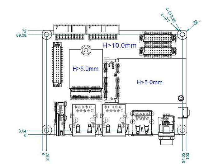
机械尺寸 ( Mechanical Characteristics)
快速入门 (Quick Start)
系统下载 (OS Download)
Debug port 連接與設定(Debug Port Connection and Setting)
- RSB-3810 debug port is shared with COM1. Please connect the debug console cable 1700034345-01 & 1700019474. Then connect the USB-to-RS232 Cable to your PC terminal. Connect the cable to COM1 pin header to the nearby the HDMI connector.
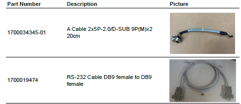
2. RSB-3810 can communicate with a host server using serial cables. Common serial communication programs such as HyperTerminal, Tera Term or PuTTY can be used in such applications. The example demonstrated below describes the serial terminal setup using Tera Term on a Windows host: Open Tera Term on your Windows PC, set the Baud rate to 921600.
燒錄方法 (Flash eMMC Method)
Password: ubuntu
Recovery Ubuntu:
Prepare:
- Prepare a Ubuntu 22.04 recovery image.
- Follow the link to install the MediaTek flash tool “ genio-tools on a Ubuntu 22.04 x86 PC.
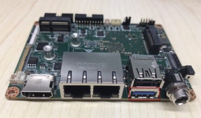
- USB typeA to typeA cable
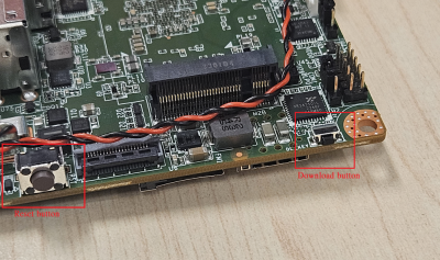
- USB typeA port, download and reset button information (screenshot below mark by color red)
Flash steps:
- To connect USB typeA to typeA cable to the host computert and the RSB-3810 typeA port
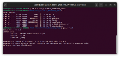
- To extract the Ubuntu recovery image:
- cd recovery package
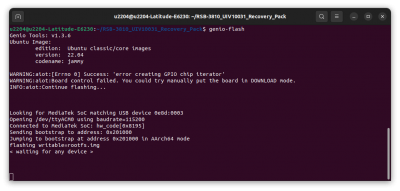
- Run "genio-flash"
- Turn the RSB-3810 board power on
- press Download button and hold it
- Press and release the reset button
- Release the Download button after the tool outputs "< waiting for any device >"
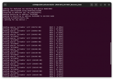
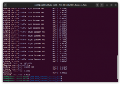
- The flash tool will continue to flash recovery image.
Linux系统的基本使用(Linux System Basic Operating Method)
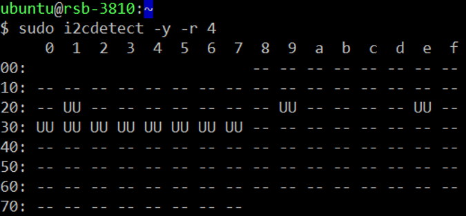
I2C Setting (RSB-3810)
Step 1: install required software sudo apt update sudo apt install i2c-tools Step 2: check if the devices are on the specified bus sudo i2cdetect -y -r 4
Display Setting (RSB-3810)
HDMI TX:
Single Display HDMI (default) u-boot:
setenv DISPLAY hdmi.dtbo saveenv reset
Dual Channel LVDS panel G215HVN0 u-boot:
setenv DISPLAY lvds0.dtbo saveenv reset
ubuntu: (root permission)
sudo i2cset -f -y 2 0x20 0x81 0x0b b (sudo i2cset -f -y 2 0x20 0x81 0x1b b) /* 0b: VESA 24 bpp, 1b: JEIDA 24 bpp */ sudo i2cset -f -y 2 0x20 0x84 0x01 b sudo i2cset -f -y 2 0x20 0x85 0x00 b sudo i2cset -f -y 2 0x20 0xe8 0x01 0x78 0x45 0x56 i sudo reboot
Single Channel LVDS panel G070VW01 u-boot:
setenv DISPLAY lvds2.dtbo saveenv reset
ubuntu: (root permission)
sudo i2cset -f -y 2 0x20 0x81 0x00 b (sudo i2cset -f -y 2 0x20 0x81 0x10 b) /* 00: VESA 24 bpp, 10: JEIDA 24 bpp */ sudo i2cset -f -y 2 0x20 0x84 0x05 b sudo i2cset -f -y 2 0x20 0x85 0x02 b sudo i2cset -f -y 2 0x20 0xe8 0x01 0x78 0x45 0x56 i sudo reboot
Dual Display HDMI + Dual Channel LVDS panel G215HVN0 u-boot:
setenv DISPLAY hdmi.dtbo lvds0.dtbo saveenv reset
ubuntu:
sudo i2cset -f -y 2 0x20 0x81 0x0b b sudo i2cset -f -y 2 0x20 0x84 0x01 b sudo i2cset -f -y 2 0x20 0x85 0x00 b sudo i2cset -f -y 2 0x20 0xe8 0x01 0x78 0x45 0x56 i sudo reboot
HDMI + Single Channel LVDS panel G070VW01 u-boot:
setenv DISPLAY hdmi.dtbo lvds2.dtbo saveenv reset
ubuntu:
sudo i2cset -f -y 2 0x20 0x81 0x00 b sudo i2cset -f -y 2 0x20 0x84 0x05 b sudo i2cset -f -y 2 0x20 0x85 0x02 b sudo i2cset -f -y 2 0x20 0xe8 0x01 0x78 0x45 0x56 i sudo reboot
Audio使用方法(Audio Testing Method):
HDMI Audio
TX: Setting-->Sound-->Output Device: HDMI/DP output - Build-in Audio-->Test
Line-Out/Speaker
TX: Setting-->Sound-->Output Device: Earphone speaker - Build-in Audio-->Test
Mic-In
sudo add-apt-repository ppa:audio-recorder/ppa sudo add-apt-repository ppa:ubuntuhandbook1/audio-recorder sudo apt install audio-recorder
Source: Build-in Audio Earphone microphone +
M.2使用方法(M.2 Testing Method):
KeyE:
PCIe 3.0
lspci # WIFI
USB 2.0
lsusb # Bluetooth sudo cat /sys/kernel/debug/usb/devices
KeyB:
USB 3.0
lsusb # 5G
- WiFi
Setting-->Network
ifconfig ping -c4 8.8.8.8
- Bluetooth
Setting-->Bluetooth
- 5G
mmcli --list-modems mmcli -m 0
Serial port使用方法(Serial port Testing Method):
Use the on-board UART (/dev/ttyS2) as example
- RS-232 Loopback Test:
- Setting:
sudo bash -c " echo 328 > /sys/class/gpio/export 2> /dev/null echo 327 > /sys/class/gpio/export 2> /dev/null echo out > /sys/class/gpio/gpio328/direction echo out > /sys/class/gpio/gpio327/direction # default settings echo 1 > /sys/class/gpio/gpio328/value echo 0 > /sys/class/gpio/gpio327/value "
- Test:
# sudo stty -F /dev/ttyS2 -echo -onlcr 115200 raw # echo "RS-232 test" | sudo tee /dev/ttyS2 > /dev/null
- RS-422 Test:
- Setting:
Adam-4520 RX- <--> DB9 Pin 1 Adam-4520 RX+ <--> DB9 Pin 2 Adam-4520 TX- <--> DB9 Pin 4 Adam-4520 TX+ <--> DB9 Pin 3
sudo bash -c " echo 328 > /sys/class/gpio/export 2> /dev/null echo 327 > /sys/class/gpio/export 2> /dev/null echo out > /sys/class/gpio/gpio328/direction echo out > /sys/class/gpio/gpio327/direction echo 1 > /sys/class/gpio/gpio328/value echo 1 > /sys/class/gpio/gpio327/value "
- Test:
sudo stty -F /dev/ttyS2 speed 115200 ignbrk -brkint -icrnl -imaxbel -opost -onlcr -isig -icanon -iexten -echo -echoe -echok -echoctl -echoke
echo "RS-422 Test" > /dev/ttyS2
- RS-485 Test:
- Setting: Adam-4520 Data- <--> DB9 Pin 1 Adam-4520 Data+ <--> DB9 Pin 2
sudo bash -c " echo 328 > /sys/class/gpio/export 2> /dev/null echo 327 > /sys/class/gpio/export 2> /dev/null echo out > /sys/class/gpio/gpio328/direction echo out > /sys/class/gpio/gpio327/direction echo 0 > /sys/class/gpio/gpio328/value echo 1 > /sys/class/gpio/gpio327/value "
- Test:
sudo stty -F /dev/ttyS2 speed 115200 ignbrk -brkint -icrnl -imaxbel -opost -onlcr -isig -icanon -iexten -echo -echoe -echok -echoctl -echoke
echo "RS-485 Test" > /dev/ttyS2
I2C使用方法(I2C Test Method):
Step 1: Check i2c device
Step 2: I2c set and get
console:/ # i2cdetect -y -a 4
USB: USB disk test (USB 2.0/ USB 3.2 Gen 1 By 1 port)
check if the USB device is mount automatically
lsblk
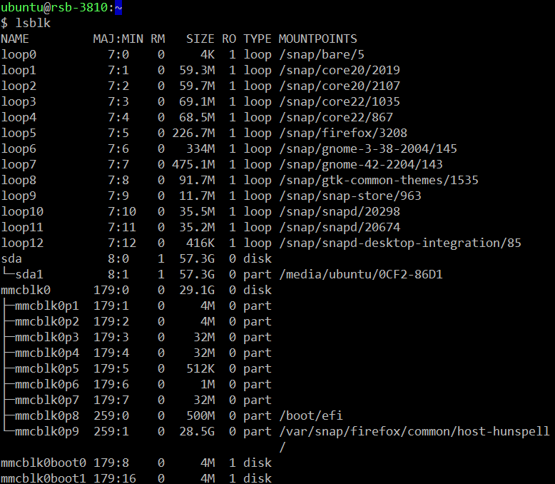
if USB device is not mount automatically
use /dev/sda1 as example
sudo mkdir -p /mnt/tmp
sudo mount /dev/sda1 /mnt/tmp
RTC使用方法(RTC Test Method):
Step 1: Set system time to current, then write to RTC
# date 041610362025 && hwclock -w && date
Step 2: Set one incorrect time, then read time from RTC to verify
# date 113009362023 && hwclock -r
Step 3: Restore the RTC time to system time
# date && hwclock -s
Step 4: Check the system and RTC time
# date && hwclock -r
eMMC/SD/SPI flash使用方法(eMMC/SD/SPI flash Testing Method):
SD
lsusb -t # get correct device node, use /dev/mmcblk1p1 as example sudo mkdir -p /mnt/tmp sudo mount /dev/ mmcblk1p1 /mnt/tmp
eMMC Ubuntu OS here
Ethernet使用方法(Ethernet Testing Method):
Step 1: Check the Ethernet device
ifconfig
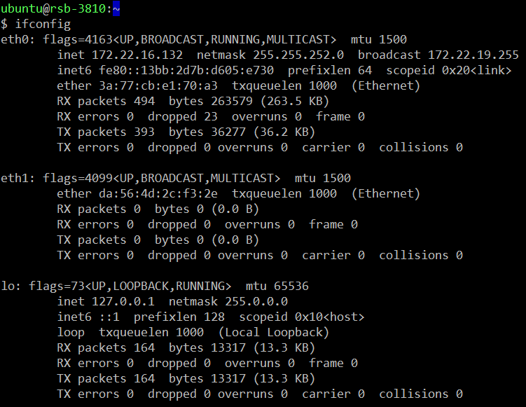
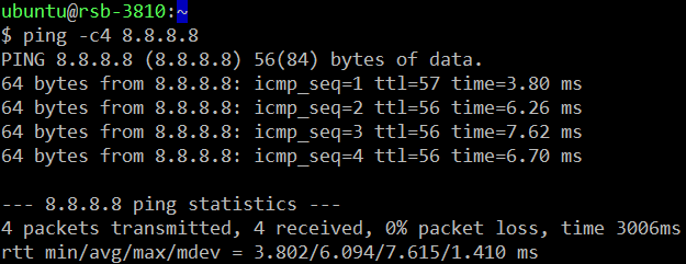
Step 2: Connect the cable and ping test (eg. Eth0)
ping -c4 8.8.8.8
GPIO使用方法(GPIO Testing Method):
- GPIO Pins:
UIO Extension 1(UIO1):
| Pin | Numbers |
|---|---|
| GPIO2 | 315 |
| GPIO4 | 316 |
UIO Extension2 (UIO2):
| Pin | Numbers |
|---|---|
| GPIO5 | 317 |
| GPIO6 | 318 |
| GPIO7 | 319 |
| GPIO8 | 320 |
| GPIO9 | 321 |
| GPIO10 | 322 |
| GPIO11 | 323 or 408 |
| GPIO12 | 324 or 409 |
- GPIO Loopback Test (Using GPIO2 and GPIO4 as examples):
Step 1: Connect GPIO2 and GPIO4 Step 2: Export GPIO interface
- echo 315 > /sys/class/gpio/export # echo 316 > /sys/class/gpio/export
Step 3: Set GPIO direction
- echo out > /sys/class/gpio/gpio1/direction # echo in > /sys/class/gpio/gpio2/direction
Step 4: Read value and set output value than check
- cat /sys/class/gpio/gpio2/value 0 # echo 1 > /sys/class/gpio/gpio1/value # cat /sys/class/gpio/gpio2/value 1
Watchdog使用方法(Watchdog Testing Method):
- Internal Watchdog:
System will reboot after 30 sec
echo 1 | sudo tee /dev/watchdog # or /dev/watchdog0
- External Watchdog:
System will reboot after 60 sec
echo 1 | sudo tee /dev/watchdog1
LED ON/OFF 使用方法(LED ONOFF Testing Method):
LED ON:
echo 255 | sudo tee /sys/class/leds/user/brightness
LED OFF:
echo 0 | sudo tee /sys/class/leds/user/brightness
UIO-4030使用方法(UIO-4030 Testing Method):
Switch to root: $ sudo su
| 1 | UART(COM_3) | # stty -F /dev/ttyS3 -echo -onlcr 921600 raw # cat /dev/ttyS3 & # echo "Serial Port Test" > /dev/ttyS3 or #microcom -s 921600 -X /dev/ttyS3 |
|---|---|---|
| 2 | GPIO | 4 DI & 4 DO Pins (UIO Extension_UIO2) input pin#5: gpio 317 output pin#6: gpio 318 input pin#7: gpio 319 output pin#8: gpio 320 input pin#9: gpio 321 output pin#10: gpio 322 input pin#11: gpio 323 output pin#12: gpio 324 (Note: gpio 323 & gpio 324 need to set the gpio 345 to high) |
| 3 | RS-485(COM_4) | Test RS-485 with Adam-4520. Adam-4520 Pin Data- and Pin Data+ connect to UIO-4030 COM_4 Pin 1 and Pin 2. # stty -F /dev/ttyUSB0 speed 115200 ignbrk -brkint -icrnl - imaxbel -opost -onlcr -isig -icanon -iexten -echo -echoe -echok -echoctl -echoke # cat /dev/ttyUSB0 & # echo "Serial Test" > /dev/ttyUSB0 |
| 4 | EEPROM | # echo -n $'\x06\x05\x04\x03\x02\x01' > /data/test1 # dd if=/data/test1 of=/sys/bus/i2c/devices/3-0050/eeprom # dd if=/sys/bus/i2c/devices/3-0050/eeprom of=/data/test2 conv=fsync |
| UIO-4030 | UIO extension | DSUB_9 |
|---|---|---|
| DI1 | GPIO5(317) | #1 |
| DI2 | GPIO7(319) | #2 |
| DI3 | GPIO9(321) | #3 |
| DI4 | GPIO11(323) | #4 |
| DO1 | GPIO6(318) | #6 |
| DO2 | GPIO8(320) | #7 |
| DO3 | GPIO10(322) | #8 |
| DO4 | GPIO12(324) | #9 |
UIO-4032使用方法(UIO-4032 Testing Method):
| 1 | UART COM_3:ttyS3 COM_4:ttyS1 | # stty -F /dev/ttyS3 -echo -onlcr 921600 raw # cat /dev/ttyS3 & # echo "Serial Port Test" > /dev/ttyS3 or # microcom -s 921600 -X /dev/ttyS3 # cat /dev/ttyS3 & |
|---|---|---|
| # stty -F /dev/ttyS1 -echo -onlcr 921600 raw # cat /dev/ttyS1 & # echo "Serial Port Test" > /dev/ttyS1 or # microcom -s 921600 -X /dev/ttyS1 | ||
| 2 | USB | USB disk write/read/verify pattern |
| 3 | Ethernet | # ifconfig # ping 8.8.8.8 |
| 4 | EEPROM | # echo -n $'\x06\x05\x04\x03\x02\x01' > /data/test1 # dd if=/data/test1 of=/sys/bus/i2c/devices/3-0050/eeprom # dd if=/sys/bus/i2c/devices/3-0050/eeprom of=/data/test2 conv=fsync |
UIO-4034使用方法(UIO-4034 Testing Method):
| 1 | UART COM_3:ttyS3 COM_4:ttyS1 | $ stty -F /dev/ttyS3 -echo -onlcr 921600 raw $ cat /dev/ttyS3 & $ echo "Serial Port Test" > /dev/ttyS3 or $ microcom -s 921600 -X /dev/ttyS3 |
|---|---|---|
| $ stty -F /dev/ttyS1 -echo -onlcr 921600 raw $ cat /dev/ttyS1 & $ echo "Serial Port Test" > /dev/ttyS1 or $ microcom -s 921600 -X /dev/ttyS1 | ||
| 2 | CAN Bus | NA |
| 3 | EEPROM | # echo -n $'\x06\x05\x04\x03\x02\x01' > /data/test1 # dd if=/data/test1 of=/sys/bus/i2c/devices/3-0050/eeprom # dd if=/sys/bus/i2c/devices/3-0050/eeprom of=/data/test2 conv=fsync |
UIO-4036使用方法(UIO-4036 Testing Method):
(Note: Please contact Advantech to get the kernel packages for enabling the UIO-4036 Ethernet switch)
| 1 | LAN Switch | # ifconfig # ping 8.8.8.8 |
|---|---|---|
| 2 | EEPROM | # echo -n $'\x06\x05\x04\x03\x02\x01' > /data/test1 # dd if=/data/test1 of=/sys/bus/i2c/devices/3-0050/eeprom # dd if=/sys/bus/i2c/devices/3-0050/eeprom of=/data/test2 conv=fsync |
UIO-4038使用方法(UIO-4038 Testing Method):
| 1 | LAN0(WAN) | # ifconfig |
|---|---|---|
| 2 | LAN | # ping 192.168.100.1 |
| 3 | EEPROM | # echo -n $'\x06\x05\x04\x03\x02\x01' > /data/test1 # dd if=/data/test1 of=/sys/bus/i2c/devices/3-0050/eeprom # dd if=/sys/bus/i2c/devices/3-0050/eeprom of=/data/test2 conv=fsync |
UIO-4040使用方法(UIO-4040 Testing Method):
| 1 | SSD | SSD disk write/read/verify pattern Disk /dev/sda: 119.24 GiB, 128035676160 bytes, 250069680 sectors Disk model: UIO-4040 Units: sectors of 1 * 512 = 512 bytes Sector size (logical/physical): 512 bytes / 512 bytes I/O size (minimum/optimal): 512 bytes / 512 bytes |
|---|---|---|
| 2 | EEPROM | # echo -n $'\x06\x05\x04\x03\x02\x01' > /data/test1 # dd if=/data/test1 of=/sys/bus/i2c/devices/3-0050/eeprom # dd if=/sys/bus/i2c/devices/3-0050/eeprom of=/data/test2 conv=fsync |
安裝AI SDK使用方法(Install AI SDK):
Install AI SDK
Install Genio Hardware Support Packages
Install Mediatek hdmirx-tool:
$ sudo apt-add-repository ppa:mediatek-genio/genio-public
$ sudo apt install mediatek-apusys-firmware-genio1200
$ sudo apt install mediatek-hdmirx-tool
通用方法(General Method)
讀取溫度(Read Thermal):
$ i=0 ; while
$i -lt 18
; do (type=cat /sys/class/thermal/thermal_zone$i/type ; temp=cat /sys/class/thermal/thermal_zone$i/temp ; echo "$i $type : $temp"); i=$((i+1));done ; sleep 0.1;
loop:
$ while; do i=0 ; while
$i -lt 18
; do (type=cat /sys/class/thermal/thermal_zone$i/type ; temp=cat /sys/class/thermal/thermal_zone$i/temp ; echo "$i $type : $temp"); i=$((i+1));done ; sleep 0.1; done
- thermal_zone0 通常會是 soc_max : 會取 soc 內部最高的溫度當作數值(Use the highest thermal in the SOC)
- cpu_big1-4 對應的就會是 A78 ( Should A78 1-4 core)<u5:p></u5:p>
- cpu_little1-4 對應的就會是 A55 (Should A55 1~4 core)<u5:p></u5:p>
ToolChain
64-bit ARM
For 64-bit ARM, the toolchain prefix is aarch64 and usage is:
<code>sudo apt install gcc-aarch64-linux-gnu
aarch64-linux-gnu-gcc -o xxxxx.out xxxxx.c</code>
or Compile the source code in RSB-3810
BSP編譯方法(BSP Compile Method)
NA