ROM-8720 User Manual
Introduction
From ESS-WIKI.
產品介紹 (Product Introduction)
產品特性 (Product Features)
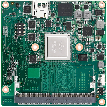
- NXP LS1046A Cortex-A72 COM Express Type 7 Computer-on-Module
- COM Express Type 7 Compact Module
- Up to 4 Cores, 1.6 GHz
- One Channel DDR4 SODIMM, max. 16 GB (ECC & Non-ECC)
- Up to 10GbE x2 and GbE x4
- PCIe 3.0 x3, PCIe 2.0 x2, USB 3.0 x3 and USB 2.0 x2
- Support Ubuntu BSP
產品官網連結 (Product Official Website Link)
ROM-8720 產品頁面連結
硬體接口說明 (Hardware Interface Introduction)
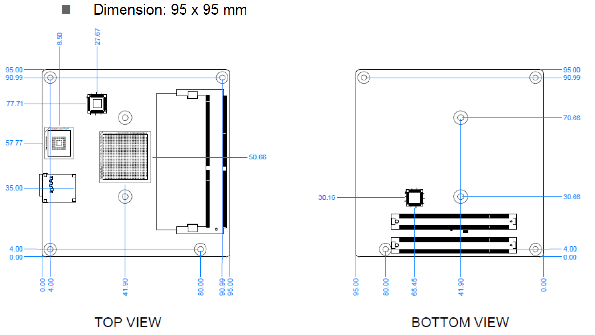
接口布局和尺寸 (Layout and Sizes)
ROM-8720 接口布局圖 (Board Dimension Layout)
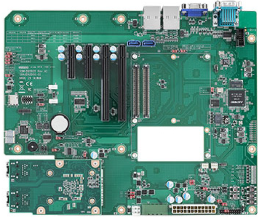
SOM-DB5920-00A1 接口布局圖 (Board Dimension Layout)
主板插針排序方式 (Pin Header Definition)
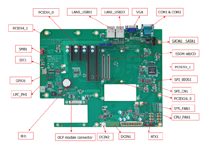
Connector List
| Position | Description |
|---|---|
| ATX1 | ATX Connector |
| CN1 | COM Express Connector |
| COM1 | UART Connector (Tx, Rx) |
| COM2 | UART Connector (Tx, Rx) |
| DCIN1 | Wide Range DC Input Connector1 |
| GPIO1 | GPIO Pin Header |
| I2C1 | I2C Wafer Box |
| LAN0_USB01 | LAN0, USB3.0/2.0 Port0 and Port1 Connector |
| LAN1_USB23 | LAN1, USB3.0/2.0 Port2 and Port3 Connector |
| LPC_PH1 | Low Pin Count Pin Header |
| PCIEX16_0 | PCIe x16 slot |
| PCIEX8_1 | PCIe x8 slot |
| PCIEX4_0 | PCIe x4 slot |
| BH1 | RTC Battery Connector |
| CPU_FAN1 | Smart Fan Connector |
| SMB1 | SMBus Wafer Box |
| SYS_FAN1 | System Fan Connector |
| SPI_CN1 | SPI BIOS Pin Header |
| OCP connector | OCP module connector |
| SPI_BIOS1 | SPI BIOS Socket |
| DCIN2 | Wide Range DC Input Connector2 |
| PCIEX4_1 | PCIe x4 slot |
| SATA0 | SATA Connector |
| SATA1 | SATA Connector |
| VGA | CRT Connector |
Jumper, Switch, Button List
| Position | Description |
|---|---|
| J8, J9 | SOM-DB5920 Voltage Input (VIN) Selection |
| J11 | COMe Module +V5SB supply |
| J14 | ATX / AT Mode Selection |
| J15 | Carrier Board SPI power supply |
| J16 | Front Panel Connector |
| J18 | Normal Operation / Clear CMOS Selection |
| J19 | BMC software Enable / Disable Selection |
| J100 | OCP 10G Fiber & Copper SEL |
| J101 | OCP I2C & MDIO SEL |
| J102 | PCIE1X0 to PCIEX4 slot & BMC SEL |
| J103 | PCIE1X4 to PCIEX4 slot & BMC SEL |
| J104 | USB2 & 3 Port to LAN_USB_23 & BMC SEL |
| J106 | LPC Pin Header Reset SEL |
| SW_LPC_TPM1 | TPM Enable / Disable Switch |
| SW_LPC_TPM2 | TPM Enable / Disable Switch |
| CB_PWROK | PWROK Signal Pull Down or Floating Selection |
| PWRBTN1 | Power Button |
| RESET1 | Reset Button |
| SLEEP1 | Sleep Button |
| EXT_THRM_1# | External Thermal Trip Button |
| WAKE_1# | Wake Button |
| LID1 | LID Button |
| RAPID1 | Rapid shutdown button |
機械尺寸 (Mechanical Characteristics)
ROM-8720
快速入門 (Quick Start)
系統下載 (OS Download)
Linux 系統 (Linux OS)
OS Support List (based on Ubuntu 18.04)
Flash Images to SD/USB.
The SD/eMMC share the same path so the system can only boot either SD or eMMC.
These operations are processed on a Linux host.
建立可開機 SD 卡 (Bootable SD card)
cd $images_folder
sudo flex-installer -i pf -d /dev/sda
sudo flex-installer \
-f firmware_ls1046arom8720_s1_uboot_sdboot.img \
-b bootpartition_LS_arm64_lts_5.4_xxxxxxxxxxxx.tgz \
-r rootfs_lsdk2012_ubuntu_main_arm64.tgz \
-d /dev/sda
sync
*`*Rootfs and Boot-Partition in USB*`*
cd $images_folder
sudo flex-installer -i pf -d /dev/sdx
sudo flex-installer \
-b bootpartition_LS_arm64_lts_5.4_xxxxxxxxxxxx.tgz \
-r rootfs_lsdk2012_ubuntu_main_arm64.tgz \
-d /dev/sdx
sync
### *`*Debug 串口調試 (Debug port Setting)*`*
1. Connect RS-232 Cable (1700019474) to debug port (COM1)(up side) on SOM-DB5920.
2. Connect it to your PC with RS-232 Cable (1700019474).
3. J14 need to set to AT mode
4. root/root
SW1:
1:on 2:off: SD boot (Default setting)
1:off 2:off: QSPI boot (For boot from USB to flash image to eMMC)
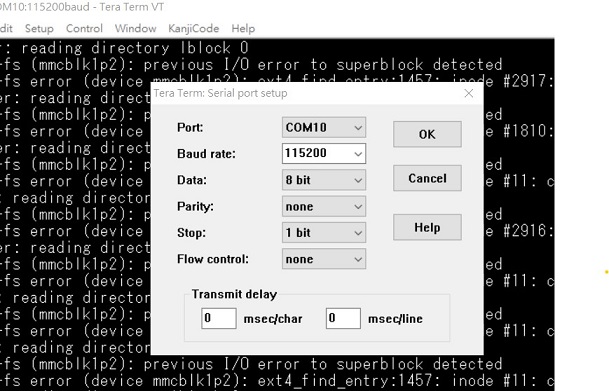
以 Tera Term 为例介绍如何使用串口调试功能
``` Baud Rate波特率:115200
Data 数据位:8
Parity 奇偶校验:无
Stop 停止位:1
Flow Control流控:无
Tera Term Tool
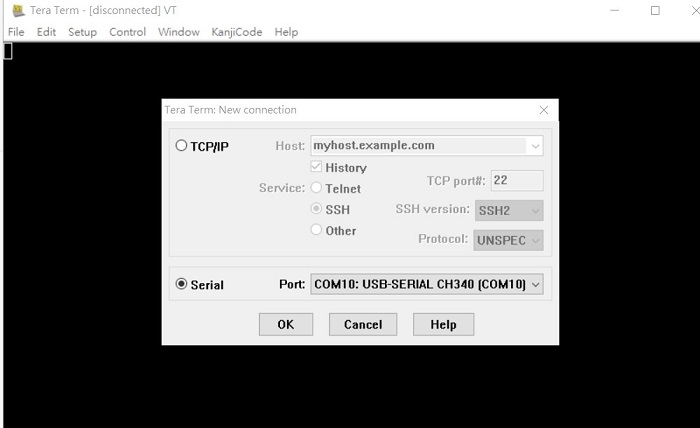
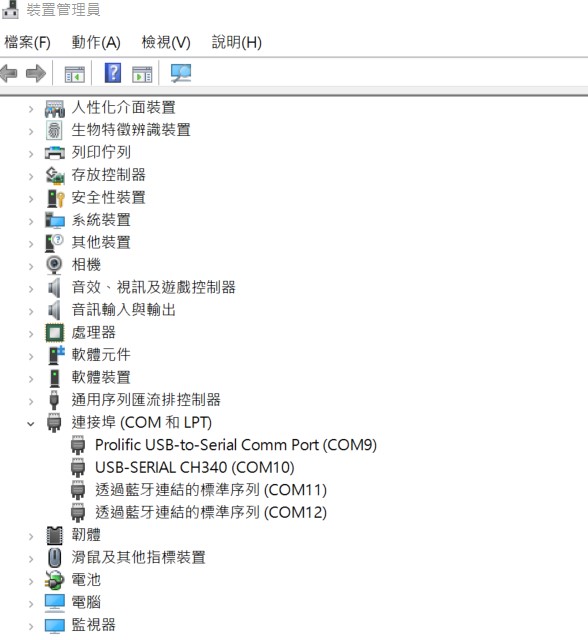
Check the Sriel port in Device Manager (查看PC端的串口号):
if you can not identify the Serial device , please check your serial driver.
Debug port connection (串口連接)
Log into Terminal Tool (进入串口调试终端):
*Linux系统的基本使用(Linux System Basic Operating Method)*
*乙太網路使用方法(Ethernent Testing Method)*
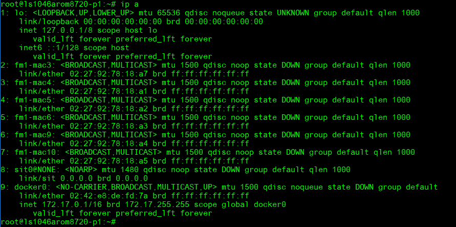
*LAN function check*
CN12 (down): fm1-mac3
CN12(up): fm1-mac4
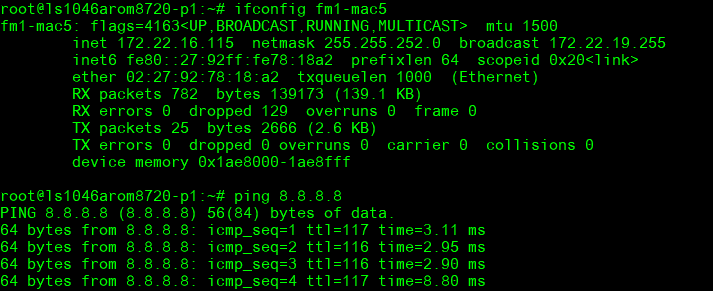
CN13(down): fm1-mac5
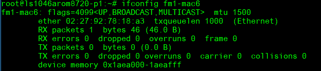
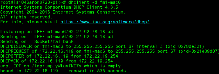
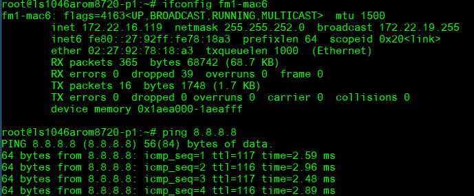
CN13(up): fm1-mac6
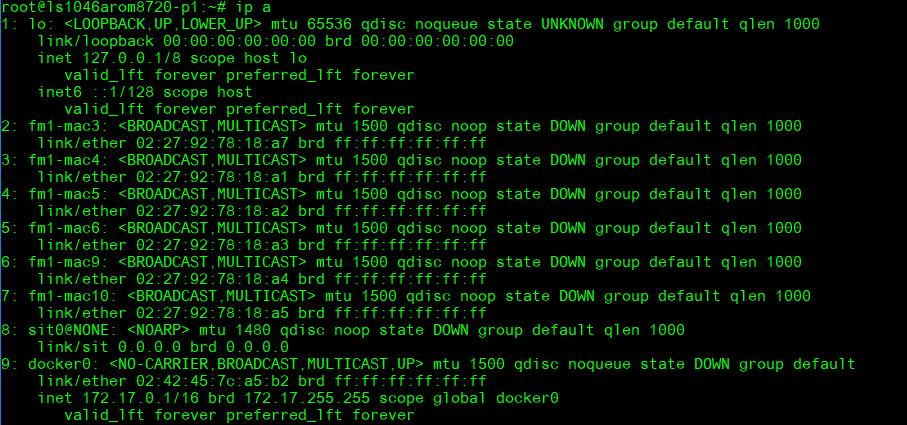
Command :
ip a
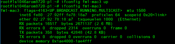
Up and ping with I/F fm1-mac3:
ifconfig fm1-mac3 up
dhclient –d fm1-mac3
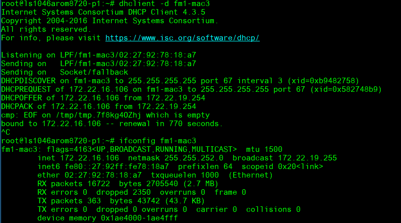
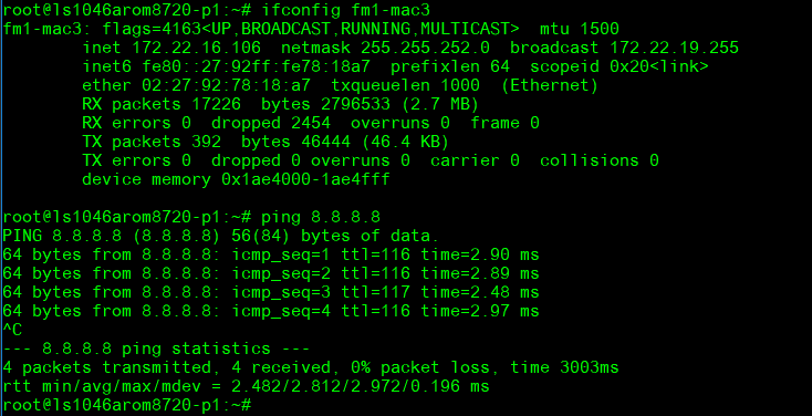
ping 8.8.8.8
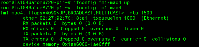
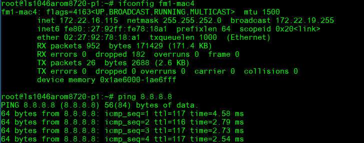
Up and ping with I/F fm1-mac4:
ifconfig fm1-mac4 up
- dhclient –d fm1-mac4
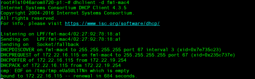
ping 8.8.8.8
Up and ping with I/F fm1-mac5:
ifconfig fm1-mac5 up
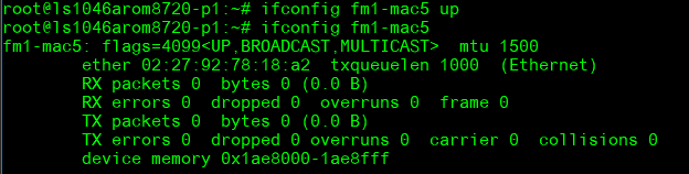
dhclient –d fm1-mac5
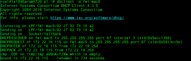
ping 8.8.8.8
Up and ping with I/F fm1-mac6:
ifconfig fm1-mac6 up
dhclient –d fm6-mac6
ping 8.8.8.8
*ROM-EG60 Function:*
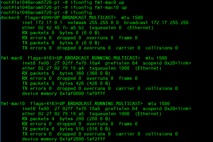
**** RJ45_CN1: fm1-mac9
RJ45_CN2: fm1-mac10
**Command : ip a **
-
ifconfig fm1-mac9 up
-
ifconfig fm1-mac10 up
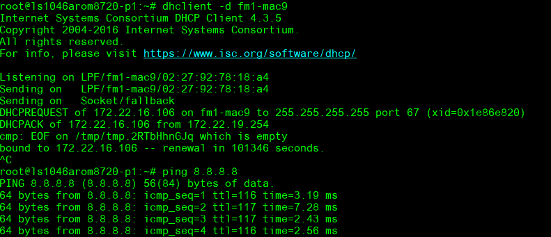
Up and ping with I/F fm1-mac9:
dhclient –d fm1-mac9
ping 8.8.8.8
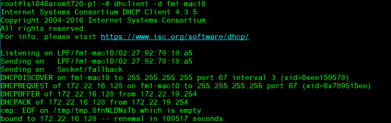
- Up and ping with I/F fm1-mac10:
dhclient –d fm1-mac10
#ping 8.8.8.8
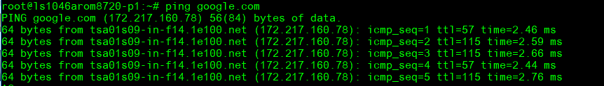
Ping google.com
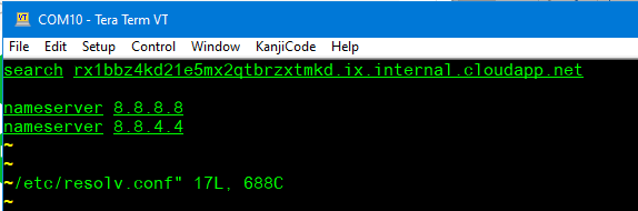
Edit /etc/resolv.conf to add nameserver
- ping google.com
*WiFi使用方法(WIFI Testing Method)*
Test WIFI (EWM-W168)
Connect mini PCIe to PCIe
Connect to SOM-1A10 PCIE2 or 3
The I/F may different with the PCIE slot
I/F:
wlP1p1s0(PCIE2) or wlP2p1s0(PCIE3)
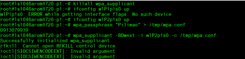
Need to install wpa_supplicant first
Up and ping with I/F wlP1p1s0:
-
killall wpa_supplicant
-
ifconfig wlP2p1s0 up
-
wpa_passphrase "Pilimao" "0913079939" > /tmp/wpa.conf
wpa_supplicant -BDwext -i wlP2p1s0 -c /tmp/wpa.conf
Request IP Addr:
- dhclient -d wlP2p1s0
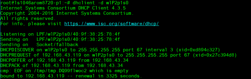
- ping 8.8.8.8:
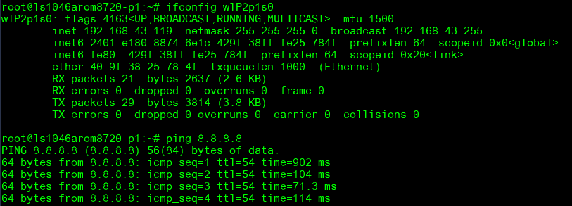
Add nameserver:
-
vi /etc/resolv.conf
-
ping google.com:

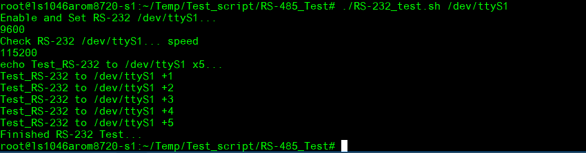
*串口使用方法(Serial Port Operating Method)*
RS-232 test: Connect RS-232 loopback
COM2: /dev/ttyS1
Test script:
<span lang="EN-US" style="color:black">#set -x #echo on</span>

<span lang="EN-US" style="color:black">echo "Enable and Set RS-232 $1..."</span>

<span lang="EN-US" style="color:black">stty -F $1 speed 115200 -onlcr -echo</span>

<span lang="EN-US" style="color:black">sleep 1</span>

<span lang="EN-US" style="color:black">echo "Check RS-232 $1... speed"</span>

<span lang="EN-US" style="color:black">stty -F $1 speed</span>

<span lang="EN-US" style="color:black">sleep 1</span>

<span lang="EN-US" style="color:black">echo "echo Test_RS-232 to $1 x5..."</span>

<span lang="EN-US" style="color:black">sleep 1</span>

<span lang="EN-US" style="color:black">cat $1 &</span>

<span lang="EN-US" style="color:black">sleep 1</span>

<span lang="EN-US" style="color:black">for ((i=1;i<=5;i++))</span>

<span lang="EN-US" style="color:black">do</span>

<span lang="EN-US" style="color:black">    echo "Test_RS-232 to $1 +$i" > $1</span>

<span lang="EN-US" style="color:black">    sleep 0.5</span>

<span lang="EN-US" style="color:black">done</span>

<span lang="EN-US" style="font-size:11.0pt"><span style="font-family:" times",serif"=""><span style="color:black">echo "Finished RS-232 Test..."</span></span></span>
# ./RS-232_test.sh /dev/ttyS1
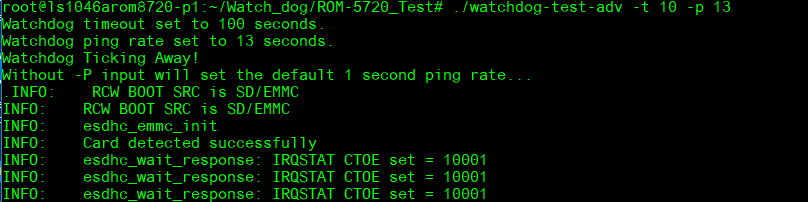
*Watch Dog Function*
System will reboot after enable watchdog and count 60 sec :
Check default watchdog time:

Enable watchdog, system will reboot after 60 sec.
- echo 1 > /dev/watchdog

System poweroff after 60 sec. cannot reboot again
Set timeout to 10 and pin rate to 13, the system will reboot after 10 seconds.
- ./watchdog-test-adv -t 10 -p 13
*RTC test*
Disable RTC sync service:
- systemctl stop systemd-timesyncd
Set system time to current, then write to RTC:
![]()
- date 110415302022 && hwclock -w && date
Set one incorrect time, then read time from RTC to verify:
![]()
- date 010100002000 && hwclock -r && date
Set the system time from the RTC:

- hwclock -s && date

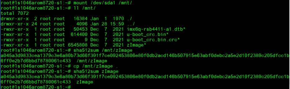
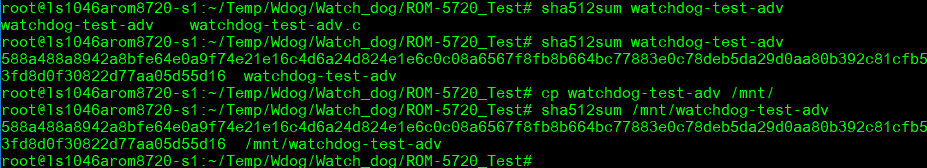
*Storage Function Test :*
*SATA DISK:*
Read/write data and compare sha512 result
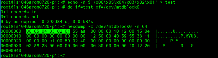
SPI Read/Write test
Write/Read/Verify data in the start/end 4 byte of flash

-
Note: Make sure the content of SPI nor flash is erased
-
echo -n $'\x06\x05\x04\x03\x02\x01' > test
-
dd if=test of=/dev/mtdblock0
-
hexdump -C /dev/mtdblock0 -n 64
*通用方法(General Method)*
*查看CPU温度(Check CPU Temperature)*
*查看CPU频率(Check CPU Frequency)*
           >> 900000
           cat /sys/devices/system/cpu/cpu0/cpufreq/cpuinfo_max_freq
           >> 1200000
*查看内存容量(Check Memory Capacity)*
*查看存储容量(Check Storage Capacity)*
*網路Ping測試(Ping Network Testing)*
     PING 8.8.8.8 (8.8.8.8) 56(84) bytes of data.
     64 bytes from 8.8.8.8: icmp_seq=1 ttl=54 time=2.10 ms
     64 bytes from 8.8.8.8: icmp_seq=2 ttl=54 time=2.10 ms