產品介紹
產品特性(Features)
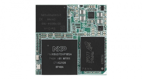
- NXP Arm® Cortex®-A35 i.MX 8ULP Dual up to 1.0 GHz
- 1 x Arm Cortex-M33 core
- Onboard LPDDR4 1GB, 2000MT/s memory
- 1 x 4 lane MIPI-DSI 1 x USB2.0, 1 x USB 2.0 OTG, 5 x UART, 2 x I2C, 24 x GPIO, 6 x PWM, 1 x CAN
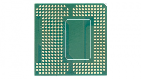
- Ultra small size form factor - OSM
- Support Ycoto Linux and Microsoft Azure Sphere OS
產品官網連結(Product information Link)
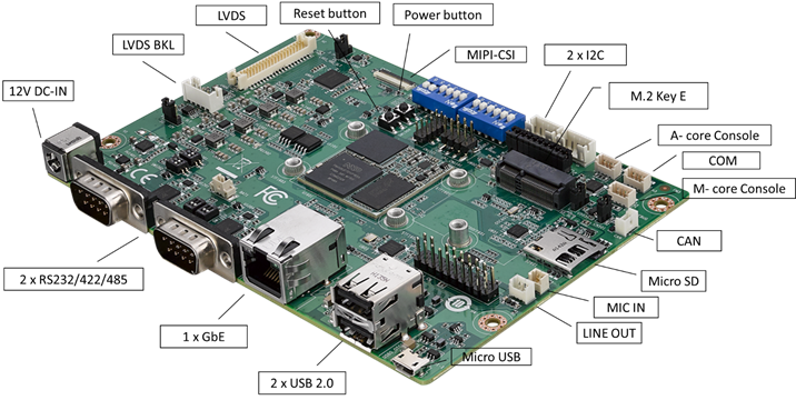
接口布局和尺寸(Layout and Sizes)
ROM-2620 接口布局圖 Board Dimension Layout
ROM-ED91 接口布局圖 Board Dimension Layout
主板内置插针式引脚排序方式 (Pin Header defination)
Internal I/O, Jummper/Switch List:
| Label | Function | Label | Function |
| DCIN1401 | 12V DCIN connector | SW1301 | BT0_CFG1/4, BT1_CFG6/7/9/11 |
| COMB | RS232/422/485 | SW1302 | BT0_CFG0, BT1_CFG4/5, BOOT_SEL0#/1#, MOD_ON |
| COMA | RS232/422/485 | SW1203 | UARTB_MODE0, UART_MODE1 |
| LAN | LAN Connector | SW1204 | UARTB_TERM, UARTB_SLEW |
| USB1 | USB2.0 port Connector | SW1206 | U1205_RX_TERM, U1205_MODE2 |
| USB0_OTG1 | Micro USB Connector | SW1201 | UARTA_MODE0, UART_MODE1 |
| AJ | Line Out Connector | SW1202 | UARTA_TERM, UARTA_SLEW |
| MIC | MIC Connector | SW1205 | U1202_RX_TERM, U1202_MODE2 |
| CAN | CAN Bus Connector | SW1303 | Power button |
| COME_DEBUG | M-core debug console | SW1304 | Reset button |
| COMC | COM | I2S_CN | I2S Connector |
| COMD | A-core debug console | CN501 | CAN0_H, CAN0_L terminatl resistors |
| I2C1101 | I2C Connector | SD_SLT | SD select |
| I2C1102 | I2C Connector | GPIO1101 | GPIO header |
| CN601 | M.2 Key E Connector | SPI_CN1101 | PWM header |
| CN701 | MIPI-CSI Connector | CN1101 | SPI header |
| LVDS | LVDS Connector | LVDS_VDD_SLT | LVDS power select select header |
| LVDS_BKLT_PWR | LVDS Backlight Connector | LVDS_BKLT_SLT | LVDS Backlight power select header |
| BAT1 | Battery Connector |
Rear I/O
LED Function List
| Location | Function |
| PD1405 | +V5_MOD |
| PD1502 | +V3.3 |
| PD1503 | +V5 |
接口引脚定義 (Connector Pin definitions)
- DCIN1401
- COMB
- COMA
- LAN
- USB1
- USB0_OTG1
- AJ(Audio_Jack)
- MIC
- CAN
- COME_DEBUG(M-core_debug)
- COMC
- COMD(A-code_debug)
- I2C1101
- I2C1102
- CN601(M.2_Key_E)
- CN701(MIPI-CSI)
- LVDS
- LVDS_BKLT_PWR
- BAT1
- I2S_CN(I2S)
- CN501(CAN0_H/CAN0_L)
- GPIO1101
- SPI_CN1101(PWM)
- CN1101(SPI)
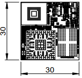
**机械尺寸 (**Mechanical Characteristics)
ROM-2620
快速入门 (Quick Start)
系统下载 (OS Download)
- 'Linux系统 (Linux OS)'
**Yocto 4.0:**IoTGateway/BSP/Linux/iMX8/OS Support List 4.0 release ROM-2620 - ESS-WIKI (advantech.com.tw)
**Yocto 4.2:**IoTGateway/BSP/Linux/iMX8/OS Support List 4.2 release ROM-2620 - ESS-WIKI (advantech.com.tw)
Linux 燒錄方法 (Linux Flash eMMC Method)
使用Flash tool 燒錄鏡像到eMMC (Flash image into eMMC by Flash Tools)
Step0: 檢查SD卡在Linux 環境的代號 (check SD card symbol in Linux system)

Step1: 創造一張可開機的SD 卡 (Create a bootable SD card)
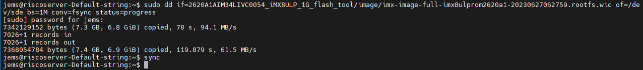
Command :
~$ sudo dd if=2620A1AIM34LIVC0054_iMX8ULP_1G_flash_tool/image/imx-image-full-imx8ulprom2620a1-20230627062759.rootfs.wic of=/dev/sde bs=1M conv=fsync status=progress
Step2: 將可開機的SD 卡插入底板SD卡卡槽(Plug the SD card into Carrier board 's SD card slot)
Step3: 確認開機選擇指撥開關
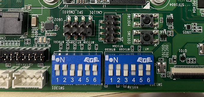
| EMMC boot: | SW1301: 1_2_5_6 ON SW1302: 4_6 ON |
| SD boot: | SW1301: 1_2_3_4 ON SW1302: 4_6 ON |
| Serial download: | SW1301: All OFF SW1302: 5_6 ON |
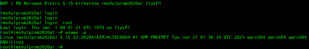
Step4:打開電源 和 終端機 (Turn on the Power & Terminal)
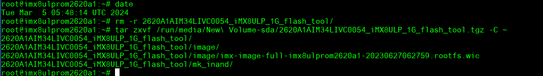
Step5: 複製flash tool到U盤中, 解壓縮flash tools檔案,(copy to USB Disk, then unzip the flash tools file)(Test with 32G SD card)
複製檔案到U盤中 (Copy the flash file to USB Disk), 解壓縮flash tool到home目錄(Unzip the file to home)
- tar zxvf /run/media/New\ Volume-sda/2620A1AIM34LIVC0054_iMX8ULP_1G_flash_tool.tgz -C ~
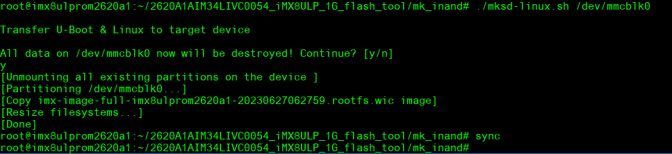
- 進入flsah tool下的mk_inand資歷夾, 執行指令./mksd-linux.sh /dev/mmcblk0燒錄image到eMMC(Connect USB Disk to ROM-2620 system, extract the flash tool and browser to mk_inand folder and execute flash shell script "./mksd-linux.sh /dev/mmcblk0"
解壓縮後如果沒有mksd-linux.sh檔案, 可以到以下連結下載並複製到mk_inand資料夾下(If there is no mksd-linux.sh file in mk_inand directory. Please download from the link below and place it in mk_inand directory:
| ROM-2620 | Device node |
| SD card | /dev/mmcblk2 |
| eMMC | /dev/mmcblk0 |
- 切換開機switch來設定成從eMMC開機(Change boot switch to boot from eMMC. Reboot system).
Debug 串口調試 (Debug port Setting)
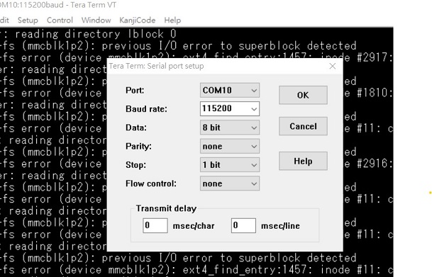
以 Tera Term 为例介绍如何使用串口调试功能
   Baud Rate波特率:115200
   Data 数据位:8
   Parity 奇偶校验:无
   Stop 停止位:1
   Flow Control流控:无
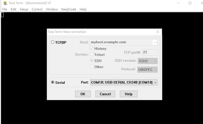
Tera Term Tool
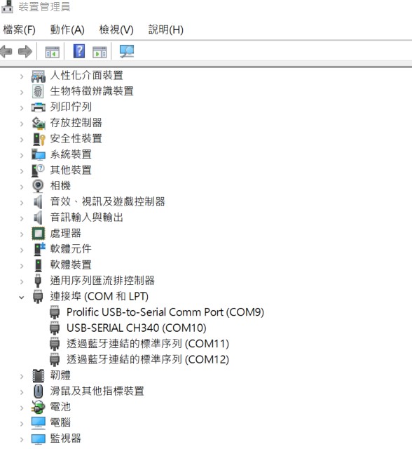
Check the Sriel port in Device Manager (查看PC端的串口号):
if you can not identify the Serial device , please check your serial driver.
Debug port connection (串口連接)
Log into Terminal Tool (进入串口调试终端):
Linux系统的基本使用(Linux System Basic Operating Method)
UUU 使用方法(USB Connection (OTG port))
Connect USB cable to USB OTG port.
Change boot switch to "SW1301 all OFF, SW1302: 5_6:on" to boot from force recovery mode.
| Serial download: | SW1301: All OFF SW1302: 5_6 ON |
Download uuu tool from link below:
Releases · nxp-imx/mfgtools (github.com)
The uuu verison we tested is 1.4.193: uuu
uuu (Universal Update Utility) for nxp imx chips -- libuuu_1.4.193-0-ge56424c
Perpare uboot and image files below:
2620A1AIM34LIVC0064_iMX8ULP_1G_imx-boot.tgz
2620A1AIM34LIVC0064_iMX8ULP_1G_flash_tool.tgz
- Download uuu
$ wget <https://github.com/nxp-imx/mfgtools/releases/download/uuu_1.4.193/uuu>
$ chmod a+x uuu
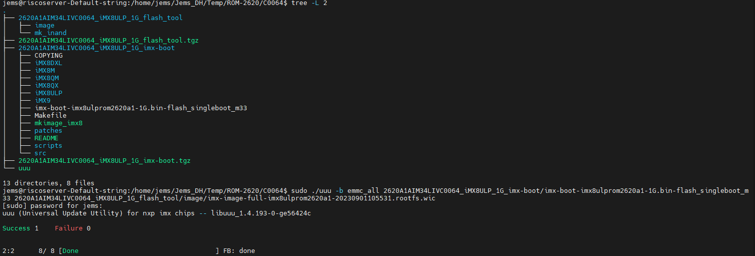
$ tar zxvf 2620A1AIM34LIVC0064_iMX8ULP_1G_imx-boot.tgz
$ tar zxvf 2620A1AIM34LIVC0064_iMX8ULP_1G_flash_tool.tgz
Type command below to flash eMMC:
$ sudo ./uuu -b emmc_all 2620A1AIM34LIVC0064_iMX8ULP_1G_imx-boot/imx-boot-imx8ulprom2620a1-1G.bin-flash_singleboot_m33 2620A1AIM34LIVC0064_iMX8ULP_1G_flash_tool/image/imx-image-full-imx8ulprom2620a1-20230901105531.rootfs.wic
Display Setting (ROM-2620)
U-boot Command :
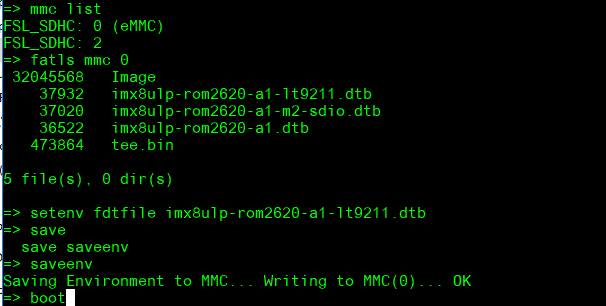
- Display
=> setenv fdtfile imx8ulp-rom2620-a1-lt9211.dtb
=> saveenv
=> boot
Audio(Audio Testing Methid)
cat /proc/asound/cards
0 [sgtl5000 ]: sgtl5000 - sgtl5000
sgtl5000
amixer set Mic 50%
amixer set Lineout 100%
amixer set PCM 100%
Record and playback:
# arecord -t wav -c 2 -r 44100 -d 10 /tmp/mic.wav
# aplay /tmp/mic.wav
M.2 WiFi/BT測試方法(M.2 WiFi/BT Testing Method)
- Test Wi-Fi with EWM-W167 on C0048 version: Change SD_SLT to 2-3
=> setenv fdtfile imx8ulp-rom2620-a1-m2-sdio.dtb
=> saveenv
=> boot
In Linux user space:
iwconfig
ifconfig wlan0 up
iwlist wlan0 scan | grep ESSID
killall wpa_supplicant
ifconfig wlan0 up
wpa_passphrase "Pilimao" "0913079939" > /tmp/wpa.conf
wpa_supplicant -BDwext -iwlan0 -c/tmp/wpa.conf
udhcpc -b -i wlan0
ping 8.8.8.8
Add name server: nameserver 8.8.8.8 in resolv.conf file
vi /etc/resolv.conf
ping google.com
Test BT:
cd /opt/rtl8723bs_bt/
./start_bt.sh ttyLP0
hciconfig hci0 up
hciconfig
bluetoothctl
discoverable on
pairable on
scan on
info 84:C5:A6:D3:AF:E4
pair 84:C5:A6:D3:AF:E4
connect 84:C5:A6:D3:AF:E4
paired-devices
disconnect 84:C5:A6:D3:AF:E4
remove 84:C5:A6:D3:AF:E4
- Test Wi-Fi with EWM-W194M201E Module (SDIO Interface)
Step 1: Press enter after boot. The system will stop at u-boot, and change dtb file by below command.
=> setenv fdtfile imx8ulp-rom2620-a1-m2-sdio-88w8997.dtb
=> saveenv
=> boot
Step 2: Install driver by below command.
rmmod mwifiex_sdio mwifiex
modprobe moal mod_para=nxp/wifi_mod_para.conf
modprobe btnxpuart
Step 3: WIFI test command.
ifconfig mlan0 up
wpa_passphrase ASUS-917C qwert12345 > /tmp/wpa.conf
wpa_supplicant -d -B -i mlan0 -c /tmp/wpa.conf
udhcpc -i mlan0
- Test Bluetooth with EWM-W194M201E Module (UART Interface)
Step 1: Please refer to above step 1.
Step 2: Please refer to above step 2.
Step 3: Bluetooth test command.
hciconfig hci0 up
bluetoothctl
discoverable on
pairable on
scan on
[NEW] FC:18:3C:8D:75:F4 myphone
scan off
pair FC:18:3C:8D:75:F4
connect FC:18:3C:8D:75:F4
Serial Port測試方法(Serial Testing Method)(COM A/C)
| COMA | /dev/ttyLP0 |
| COMB(M33 Domain) | |
| COMC | /dev/ttyLP2 |
| COMD | /dev/ttyLP1 |
| COME_DEBUG | M33 debug port |
- RS-232 Loopback Test (eg. COMA: ttyLP0):
Step 1: First change ROM-ED91 SW1201 to ‘01’.
Step 2: Run test command.
stty -F /dev/ttyLP0 speed 115200 -echo
cat /dev/ttyLP0 &
echo test > /dev/ttyLP0
- RS-422 Test:
Step 1: First change ROM-ED91 SW1201 to ‘11’.
Step 2: Test RS-422 with Adam-4520. Connect Adam-4520 with COMA with DB9 as the following:
Adam-4520 RX- ROM-2620 COMA DB9 Pin 1,
Adam-4520 RX+ ROM-2620 COMA DB9 Pin 2,
Adam-4520 TX- ROM-2620 COMA DB9 Pin 4,
Adam-4520 TX+ ROM-2620 COMA DB9 Pin 3
Step 3: Run below command:
stty -F /dev/ttyLP0 speed 115200 ignbrk -brkint -icrnl -imaxbel -opost -onlcr -isig -icanon -iexten -echo -echoe -echok -echoctl -echoke
cat /dev/ttyLP0 &
echo "Serial Test" > /dev/ttyLP0
- RS-485 Test:
Step 1: First change ROM-ED91 SW1201 to ‘10’.
Step 2: Test RS-485 with Adam-4520. Connect Adam-4520 with COMA with DB9 as the following:
Adam-4520 Data- ROM-2620 COMA DB9 Pin 1,
Adam-4520 Data+ ROM-2620 COMA DB9 Pin 2
Step 3: Run below command:
stty -F /dev/ttyLP0 speed 115200 ignbrk -brkint -icrnl -imaxbel -opost -onlcr -isig -icanon -iexten -echo -echoe -echok -echoctl -echoke
cat /dev/ttyLP0 &
echo "Serial Test" > /dev/ttyLP0
I2C測試方法(I2C Testing Method)
Step 1: Plug in ROM-EG70
Step 2: Test by below command (eg. I2C-6 I2C_1101):
modprobe at24
echo -n $'\x06\x05\x04\x03\x02\x01' > test
dd if=test of=/sys/bus/i2c/devices/6-0050/eeprom
hexdump -C /sys/bus/i2c/devices/6-0050/eeprom -n 64
USB測試方法(USB Testing Method)
USB disk test (USB 2.0)
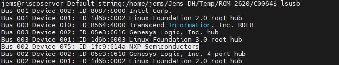
Step 1: Issue the following command (lsusb -t) after inserting a USB disk into the USB 2.0 port to check if the USB device is listed. Step 2: Test (eg. if usb disk is /dev/sda)
dd if=/dev/urandom of=data bs=1 count=1024
dd if=/dev/sda of=backup bs=1 count=1024 skip=4096 # dd if=data of=/dev/sda bs=1 seek=4096
dd if=/dev/sda of=data1 bs=1 count=1024 skip=4096 # diff data data1
dd if=backup of=/dev/sda bs=1 seek=4096
RTC測試方法(RTC Testing Method)
Step 1: Set system time to current, then write to RTC
date 021010452023 && hwclock -w && date
Step 2: Set one incorrect time, then read time from RTC to verify
# date 010100002000 && hwclock -r && date
eMMC/SD測使方法(eMMC/SD Testing Method)
Device Routes
eMMC: /dev/mmcblk0
SD: /dev/mmcblk2
Test (eg. emmc)
Step 1: Test command:
**# dd if=/dev/urandom of=data bs=1 count=1024
dd if=/dev/mmcblk0 of=backup bs=1 count=1024 skip=4096
dd if=data of=/dev/mmcblk0 bs=1 seek=4096
dd if=/dev/mmcblk0 of=data1 bs=1 count=1024 skip=4096
diff data data1
dd if=backup of=/dev/mmcblk0 bs=1 seek=4096**
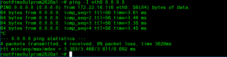
乙太網路使用方法(Ethernent Testing Method)
Command : ifconfig
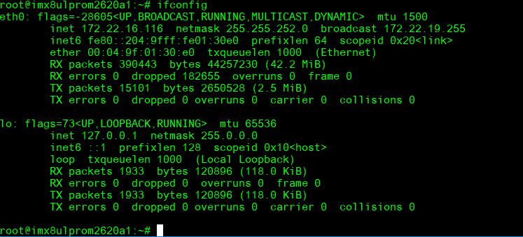
Command: Ping - I eth1 8.8.8.8 or Ping - I eth0 8.8.8.8
GPIO使用方法(GPIO Operating Method)
GPIO pin:
| GPIO1101 pin | Pin Name | CPU Ball Name | GPIO number |
| 1 | GPIO_A_0 | PTC0 | 416 |
| 2 | GPIO_A_1 | PTC1 | 417 |
| 3 | GPIO_A_2 | PTC2 | 418 |
| 4 | GPIO_A_3 | PTC3 | 419 |
| 5 | GPIO_A_4 | PTC4 | 420 |
| 6 | GPIO_A_5 | PTC12 | 428 |
| 7 | GPIO_B_0 | PTC18 | 434 |
| 8 | GPIO_B_1 | PTC19 | 435 |
| 9 | GPIO_B_2 | PTC20 | 436 |
| 10 | GPIO_B_3 | PTC21 | 437(Use for M2_SDIO_RST) |
| 11 | GPIO_B_4 | PTC22 | 438(Use for M2_W_DISABLE2) |
| 12 | GPIO_B_5 | PTC23 | 439(Use for M2_W_DISABLE1) |
| 13 | GPIO_B_6 | PTB0 | 448 |
| 14 | GPIO_B_7 | PTB1 | 449 |
| 15 | GPIO_C_0 | PTD12 | 140 |
| 16 | GPIO_C_1 | PTD13 | 141 |
| 17 | GPIO_C_2 | PTF1 | 193 |
| 18 | GPIO_C_3 | PTF7 | 199(Use for LVDS_Bridge_RST) |
| 19 | PTB6 | PTB6 | 454 |
| 20 | PTA5 | PTA5 | 485 |
GPIO Loopback Test (Using GPIO1 and GPIO2 as examples)
Step 1: Connect GPIO1 and GPIO2
Step 2: Export GPIO interface
echo 416 > /sys/class/gpio/export
echo 417 > /sys/class/gpio/export
Step 3: Set GPIO direction
echo out > /sys/class/gpio/gpio1/direction
echo in > /sys/class/gpio/gpio2/direction
Step 4: Read value and set output value than check
cat /sys/class/gpio/gpio2/value 0
echo 1 > /sys/class/gpio/gpio1/value
cat /sys/class/gpio/gpio2/value
1
Camera使用方法(Camera Testing Method)
MIPI-CSI0 (Tested with OV5640 + mini-SAS to MIPI-CSI Cable): OV5640 CSI (CN701): Connect OV5640 camera to EG-55 CAM3
Step 1: Take pictures
gst-launch-1.0 v4l2src num-buffers=1 device=/dev/video0 ! video/x-raw,width=640,height=480 ! jpegenc ! filesink location=sample.jpeg
Step 2: View on panel
gplay-1.0 sample.jpeg
PWM測試方法(PWM Testing Method)
Please use oscilloscope to check waveform.
PWM1:
echo 4 > /sys/class/pwm/pwmchip0/export
echo 1000000 > /sys/class/pwm/pwmchip0/pwm4/period
echo 500000 > /sys/class/pwm/pwmchip0/pwm4/duty_cycle
echo 1 > /sys/class/pwm/pwmchip0/pwm4/enable
PWM2:
echo 5 > /sys/class/pwm/pwmchip6/export
echo 1000000 > /sys/class/pwm/pwmchip6/pwm5/period
echo 500000 > /sys/class/pwm/pwmchip6/pwm5/duty_cycle
echo 1 > /sys/class/pwm/pwmchip6/pwm5/enable
PWM3:
echo 2 > /sys/class/pwm/pwmchip6/export
echo 1000000 > /sys/class/pwm/pwmchip6/pwm2/period
echo 500000 > /sys/class/pwm/pwmchip6/pwm2/duty_cycle
echo 1 > /sys/class/pwm/pwmchip6/pwm2/enable
PWM4:
echo 3 > /sys/class/pwm/pwmchip6/export
echo 1000000 > /sys/class/pwm/pwmchip6/pwm3/period
echo 500000 > /sys/class/pwm/pwmchip6/pwm3/duty_cycle
echo 1 > /sys/class/pwm/pwmchip6/pwm3/enable
PWM5:
echo 4 > /sys/class/pwm/pwmchip6/export
echo 1000000 > /sys/class/pwm/pwmchip6/pwm4/period
echo 500000 > /sys/class/pwm/pwmchip6/pwm4/duty_cycle
echo 1 > /sys/class/pwm/pwmchip6/pwm4/enable
M33 Function
We use default M-core firmware to verify each of IO feature. User should connect COME_DEBUG port to PC and there were show screen as demonstration below:
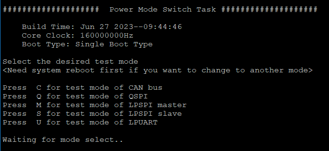
Press C for test mode of CAN bus
Press Q for test mode of QSPI
Press M for test mode of LPSPI master
Press S for test mode of LPSPI slave
Press U for test mode of LPUART
About this firmware, user should note that if you want to switch to another test mode, you must reboot the system.
CAN Bus
Step 1: Prepare two pcs rom-2620. One for ‘Node A’ one for ‘Node B’
Step 2: Connect these two boards (HI-HI/LO-LO)
Step 3: The test steps and screen are as below :
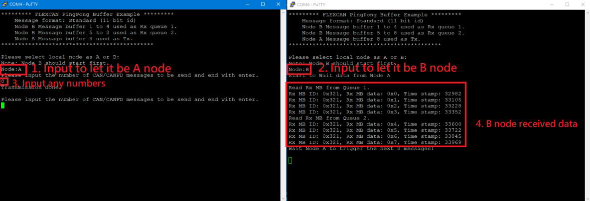
Step 4: Follow the figure (step1 - step4). If B node received data means test successful.
QSPI
Step 1: After select the test mode ‘Q’ to verify QSPI, you will see below screen.

Step 2: This test program will perform QSPI erase/write automatically and show ‘successfully’ when it’s done.
Step 3: User can press any key to run again.
LPSPI
Step 1: Two pcs rom-2620. One for ‘Master’ one for ‘Slave’.
Step 2: Connection with these two boards by SPI Bus as below:
LPSPI3_PCS0 -- LPSPI3_PCS0
LPSPI3_GND -- LPSPI3_GND
LPSPI3_PCS1 -- LPSPI3_PCS1
LPSPI3_SCK -- LPSPI3_SCK
LPSPI3_SOUT -- LPSPI3_SIN
LPSPI3_SIN -- LPSPI3_SOUT
Step 3: One board select mode ‘M’ to be Master.
Step 4: The second board is specified to Slave by select mode ‘S’.
Step 5: The test screen as below:
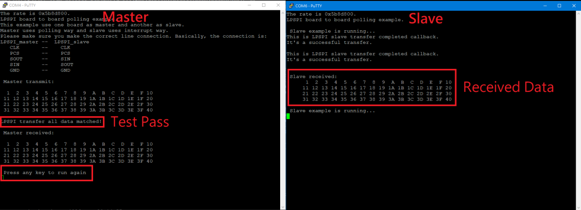
Step 6: Press any key at terminal of node master, it will execute the test again.
LPUART
Step 1: Change ROM-ED91 SW1203 to '01'.
Step 2: Connect COM-B and COM-E to PC.
Step 3: Set RTS/CTS flow control for COM-B in Putty.exe
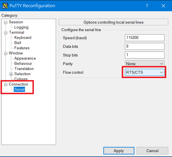
Step 4: After select the test mode ‘U’ to verify LPUART2, you will see below screen.
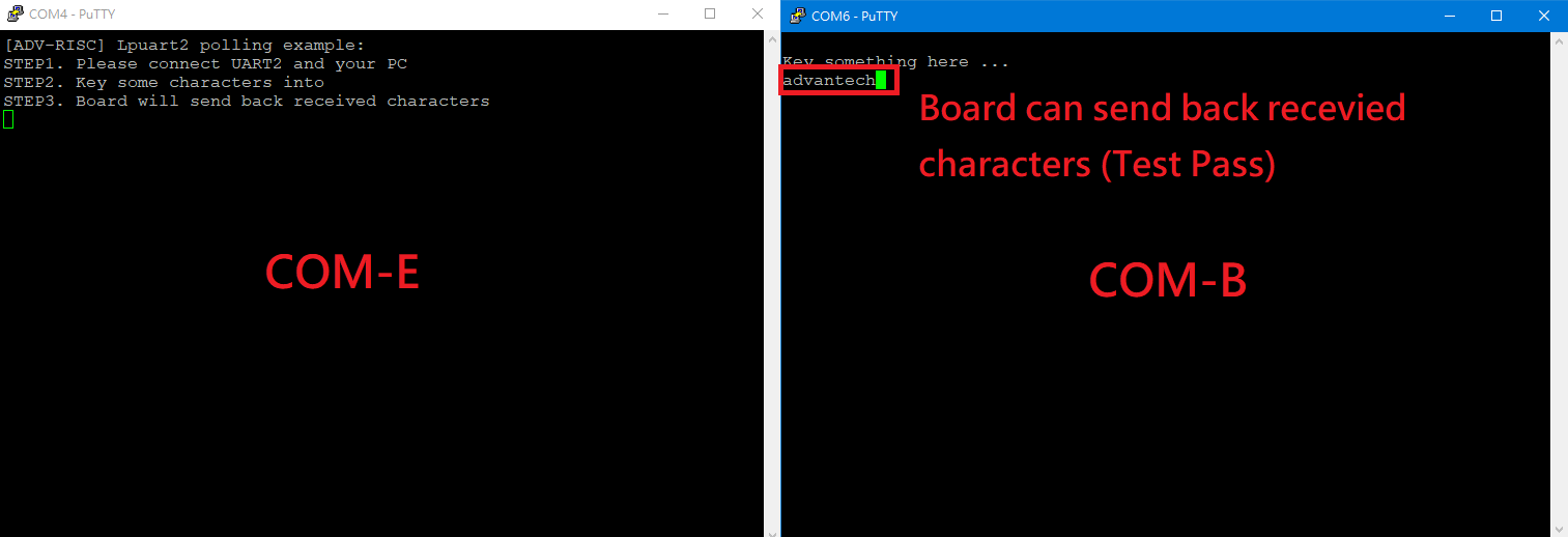
Step 5: If tester can input any characters/strings and show that at COM-B means test successful.
遠程訪問及文件傳輸(Remote Access and File Transimmion)
**查看主板IP位址 ( Chech IP Address ):**
Command : ifconfig
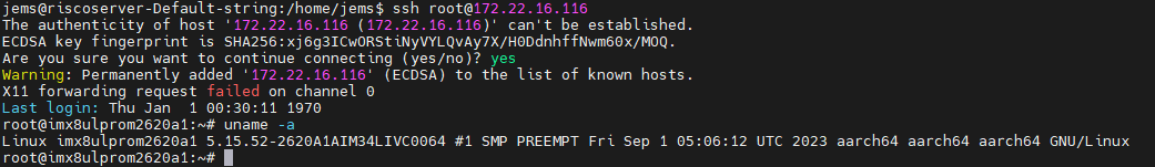
SSH访问及文件传输
SSH Remote Log into Device
- SSH远程登录,以putty选择putty.exe(或者使用Xshell、SecureCRT等类似软件)
- 需要设置远程设备的IP、通讯端口(默认22)、通讯方式,登录后验证用户名密码
通用方法(General Method)
查看CPU温度(Check CPU Temperature)
root@imx8ulprom2620a1:~# cat /sys/devices/virtual/thermal/thermal_zone0/temp
37000
查看内存容量(Check Memory Capacity)
root@imx8ulprom2620a1:~# free -h
               total        used        free      shared  buff/cache   available
Mem:           895Mi       230Mi       469Mi        29Mi       195Mi       546Mi
Swap:             0B          0B          0B
root@imx8ulprom2620a1:~#
查看存储容量(Check Storage Capacity)
root@imx8ulprom2620a1:~# df -hT
Filesystem     Type      Size  Used Avail Use% Mounted on
/dev/root      ext4       15G  3.9G  9.5G  30% /
devtmpfs       devtmpfs  431M  4.0K  431M   1% /dev
tmpfs          tmpfs     448M     0  448M   0% /dev/shm
tmpfs          tmpfs     180M   20M  160M  11% /run
tmpfs          tmpfs     4.0M     0  4.0M   0% /sys/fs/cgroup
tmpfs          tmpfs     448M   76K  448M   1% /tmp
tmpfs          tmpfs     448M  1.5M  447M   1% /var/volatile
tmpfs          tmpfs      90M  4.0K   90M   1% /run/user/0
/dev/mmcblk0p1 vfat       84M   32M   52M  38% /run/media/boot-mmcblk0p1
/dev/mmcblk2p2 ext4       29G   11G   17G  40% /run/media/root-mmcblk2p2
/dev/mmcblk2p1 vfat       84M   32M   52M  38% /run/media/boot-mmcblk2p1
root@imx8ulprom2620a1:~#
設置RTC (RTC Setting)
root@imx8ulprom2620a1:~# systemctl stop ntpdate.service
root@imx8ulprom2620a1:~# date 090816072021 && hwclock -w && date
Wed Sep  8 16:07:00 UTC 2021
Wed Mar  6 04:31:37 UTC 2024
root@imx8ulprom2620a1:~# date
Wed Mar  6 04:31:44 UTC 2024
root@imx8ulprom2620a1:~#
查看系統時間 (Check the system)
root@imx8ulprom2620a1:/# timedatectl
[ 41.402592] kauditd_printk_skb: 6 callbacks suppressed
[ 41.402611] audit: type=1334 audit(45.332:16): prog-id=15 op=LOAD
[ 41.417884] audit: type=1334 audit(45.344:17): prog-id=16 op=LOAD
Local time: Thu 1970-01-01 00:00:46 UTC
Universal time: Thu 1970-01-01 00:00:46 UTC
RTC time: Thu 1970-01-01 00:00:45 Real-Time Clock,RTC
Time zone: Universal (UTC, +0000) Time zone 目前
System clock synchronized: no
NTP service: active
RTC in local TZ: no
Note :
Change Time Zone
<code data-highlighted="yes">sudo timedatectl set-timezone "Asia/Taipei"
</code>
Local time: Fri 2024-05-03 09:07:42 CST Universal time: Fri 2024-05-03 01:07:42 UTC RTC time: Fri 2024-05-03 09:07:42 Time zone: Asia/Taipei (CST, +0800) System clock synchronized: yes NTP service: active RTC in local TZ: yes
Time Zone List
$ sudo timedatectl list-timezones
Africa/Abidjan
Africa/Accra
Africa/Addis_Ababa
Africa/Algiers
Africa/Asmara
Africa/Bamako
Africa/Bangui
Africa/Banjul
Africa/Bissau
Africa/Blantyre
Africa/Brazzaville
Africa/Bujumbura
Africa/Cairo
Africa/Casablanca