ROM-5620
產品介紹 (Product Introduction)
產品特性 (Product Features)
- NXP i.MX 8X processor with 2-4 x Arm Cortex-A35 cores
- 1 x Arm Cortex-M4F core and 1x Tensilica® HiFi 4 DSP
- Onboard 2GB LPDDR4 memory and eMMC 16GB
- 2 x single channel LVDS or 2 x 4-LANE MIPI DSI
- 1 x USB 3.0, 1 x USB 2.0 Host, 1 x USB2.0 OTG, 2 x CAN, 3 x UART, 4 x I2C, 12 x GPIO, 1 x PCIe 3.0, 1 x 4-lane MIPI CSI camera input and 2 x Gigabit LAN
- Supports OpenGL 3.0/2.1 ; OpenGL ES 3.1/3.0/2.0/1.1 and OpenCL 2.0 hardware accelerators
- Supports 4K hardware decode engine
- Low power consumption desgin
- Supports Linux and Android BSP
產品官網連結 (Product official website link)
硬件接口說明 (Hardware interface introduction)
接口布局和尺寸 (Layout and Sizes)
ROM-5620 接口布局圖 Board Dimension Layout
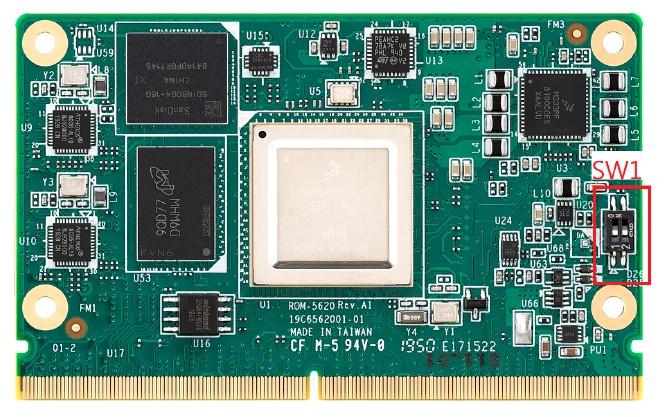
SW1:
- 1-4: ON: Normal UART. OFF: Debug Console
- 2-3: ON: AT Mode. OFF: ATX Mode
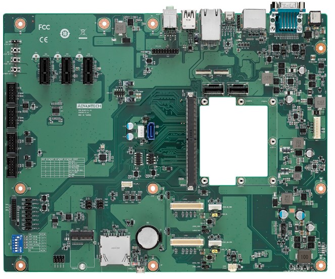
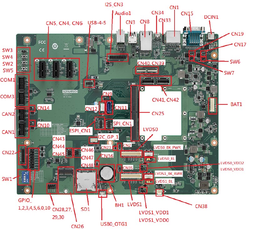
ROM-DB5901 接口布局圖 Board Dimension Layout
主板内置插针式引脚排序方式 (Pin Header defination)
Internal I/O
| Position | Description | Connector Type |
|---|---|---|
| BAT1 | PIN Header for Battery | WAFER 8P 2.54mm 180D(M) DIP A2543WV2-8P |
| BH1 | RTC Battery Holder | BATTERY HOLDER 24.923.48.9 CR2032 BH800.4GG |
| CAN1 | CANBus Port 1 | BOX HEADER 5x2P 2.54mm 180D(M) DIP 23N6960-10S10 |
| CAN2 | CANBus Port 2 | BOX HEADER 5x2P 2.54mm 180D(M) DIP 23N6960-10S10 |
| COM1 | COM Port 1 | BOX HEADER 5x2P 2.54mm 180D(M) DIP 23N6960-10S10 |
| COM3 | COM Port 3 (Debug Port) | BOX HEADER 5x2P 2.54mm 180D(M) DIP 23N6960-10S10 |
| CN4 | PCIex1 Connector 1 | PCIEXPRESS 36P 180D(F) DIP 2EG01817-D2D-DF |
| CN5 | PCIex1 Connector 2 | PCIEXPRESS 36P 180D(F) DIP 2EG01817-D2D-DF |
| CN6 | PCIex1 Connector 3 | PCIEXPRESS 36P 180D(F) DIP 2EG01817-D2D-DF |
| CN11 | SATA Connector | Serial ATA 7P 1.27mm 180D(M) DIP WATM-07DBN4A3B8 |
| CN12 | SATA Power Connector | WAFER 4P 2.5mm 180D(M) DIP 24W1161-04S10-01T |
| CN22 | GPIOx8 sets | PIN HEADER 10x2P 2.0mm 180D(M) DIP 21N22050 |
| CN25 | MXM 3.0 Connector | MXM Conn. 314P 90D(F) SMD AS0B821-S78B-7H |
| CN26 | M.2 Key E Slots | NGFF 75P 0.5mm 90D(F) H=4.2mm SMD AS0BC21-S40BE |
| CN38 | FAN (Reserved) | WTB Con. 3P 2.54mm 180D(M) DIP A2543WV0-3P-6T-5e |
| CN39 | MIPI-CSI1 (FPC, 4-Lane | FPC 39P, 0.6mm, H0.9mm |
| CN40 | MIPI-CSI0 (FPC, 2-Lane) | FPC 39P, 0.6mm, H0.9mm |
| CN41 | MIPI-CSI0 (Mini-SAS, 2-Lane) | Mini SAS 36P/0.8mm/(M)/LCP/VA/G15u/ S/BK/W |
| CN42 | MIPI-CSI1 (Mini-SAS, 4-Lane) | Mini SAS 36P/0.8mm/(M)/LCP/VA/G15u/ S/BK/W |
| ESPI_CN1 | ESPI | PIN HEADER 6x2P 2.0mm180D(M) SMD 21N22050-12M00B |
| I2C_GP_1 | I2C Pin Header | WAFER BOX 4P 2.00mm 180D(M) DIP 721-81-04TW00 |
| I2C_CN3 | Audio Codec Board | PIN HEADER 2x10P 2.54mm 180D(M) DIP 21N22564 |
| LVDS0 | LVDS0 | Wafer 2x20P/1.25mm/(M)/NY9T/VA/GFL/ S/WH/W |
| LVDS_BK_PWR | LVDS0 Back Light | WAFER BOX 5P 2.0mm 180D(M) DIP A2001WV2-5P |
| LVDS1 | LVDS1 | Wafer 2x20P/1.25mm/(M)/NY9T/VA/GFL/ S/WH/W |
| LVDS1_BK_PWR | LVDS1 Back Light | WAFER BOX 5P 2.0mm 180D(M) DIP A2001WV2-5P |
| SD1 | SD Card Slot | SD CARD 9P 90D(F) SMD WK2192CS3D- 7H |
| SPI_CN1 | SPI Pin Header | PIN HEADER 4x2P 2.54mm 180D(M) SMD 21N22564 |
| SW2 | Reset Button | TACT SW STS-091 SMD 4P H=3.8mm |
| SW4 | SLP Button | TACT SW STS-091 SMD 4P H=3.8mm |
| SW5 | Power Button | TACT SW STS-091 SMD 4P H=3.8mm |
| USB0_OTG1 | USB OTG | Micro USB 5P/0.65mm/(F)/NY9T/GFL/ RA/S/BK/B |
| USB-4-5 | USB Port 4, Port 5 | PIN HEADER 2x5P 2.0mm 180D(M) SMD 21N22050 |
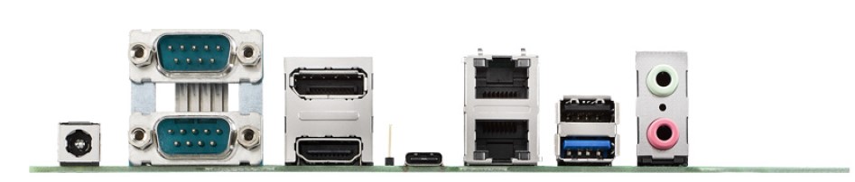
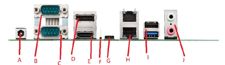
Rear I/O
| Position | Description | Name |
|---|---|---|
| DCIN | DC Jack | A |
| CN15A | UART Port 0(COM0) | B |
| CN15B | UART Port 2(COM2) | C |
| CN1A | DP Port | D |
| CN1B | HDMI Port | E |
| CN33 | Type C Controller Programming Header (Reserved Only) | F |
| CN34 | USB Type C | G |
| CN8 | GbE Ethernet Connector Port | H |
| CN3 | USB Port 1/ 2 | I |
| Audio1 | MIC Input/ Audio Output | J |
接口引脚定義 (Pin definitions)
- 電池(BAT1) & 電池扣(BH1)
- CAN(CAN1,CAN2)
- 串口(COM_DB(COM3)、COM1、UART0 、UART2)
- 显示接口(LVDS、LVDS Backlight、HDMI、DP)
- LAN接口(LAN)
- USB接口(USB1-2、USB-4-5、USB Type C、USB OTG)
- 音频接口(Audio Output & Audio Codec)
- 电源及指示灯和开关机复位按钮(Power 、LED、Power Button、Reset Button、Sleep Button)
- GPIO接口
- MINI_PCIE接口_M.2接口_SPI、I2C_接口
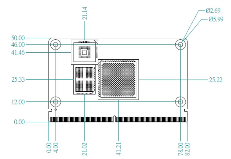
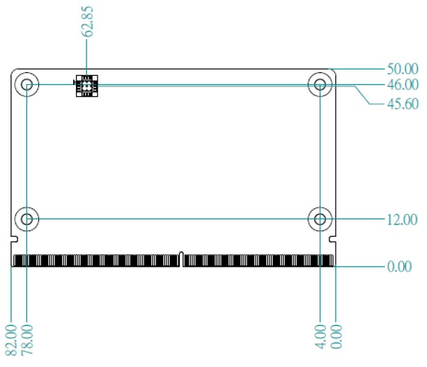
机械尺寸 (Mechanical Characteristics)
ROM-5620
快速入门 (Quick Start)
系统下载 (OS Download)
Linux 燒錄方法 (Linux Flash eMMC Method)
使用 Flash tool 燒錄鏡像到 eMMC (Flash image into eMMC by Flash Tools)
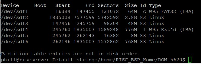
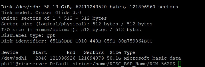
Step 0: 檢查 SD 卡在 Linux 環境的代號 (check SD card symbol in Linux system)
![]()
Step 1: 創造一張可開機的 SD 卡 (Create a bootable SD card)
![]()
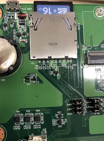
Step 2: 將可開機的 SD 卡插入底板 SD 卡卡槽 (Plug the SD card into Carrier board's SD card slot)
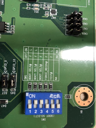
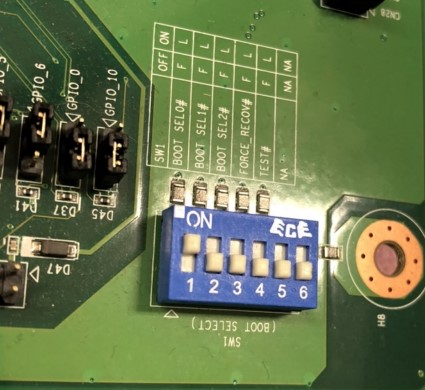
Step 3: 確認開機選擇指撥開關 SD 卡開機模式:
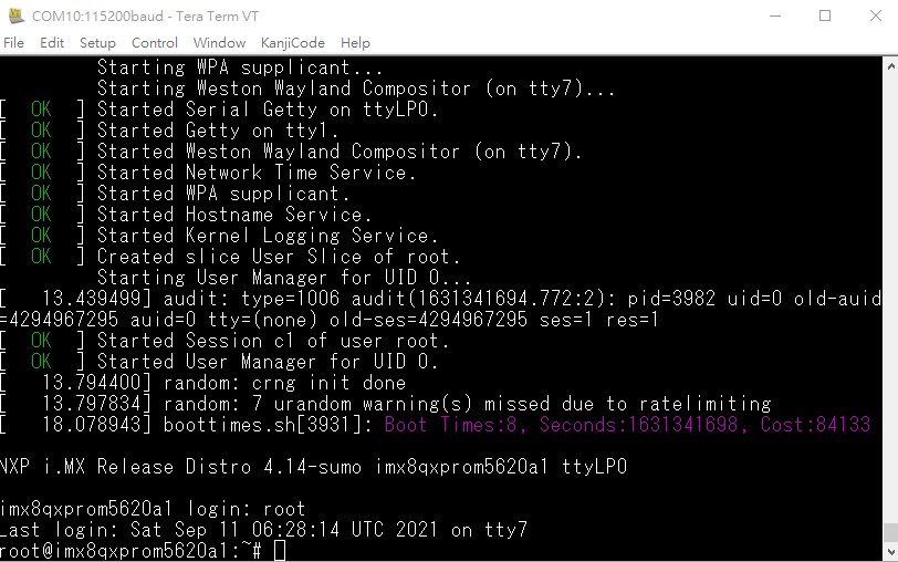
Step 4: 打開電源 和 終端機 (Turn on the Power & Terminal)
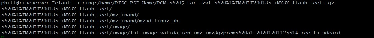
Step 5: 解壓縮 flash tools 檔案,並複製到 U 盤中 (Unzip the flash tools file, then copy to USB Disk)
解壓縮 (Unzip the file):
複製檔案到 U 盤中 (Copy the flash file to USB Disk):
- 插入 U 盤到你的 Ubuntu 電腦上 (Plug the USB Disk into you Linux PC)
- 檢視 U 盤在 Ubuntu 系統代號 (Check the USB Disk's symbol in Ubuntu System)
![]()
- 掛載 U 盤在 Ubuntu 系統中
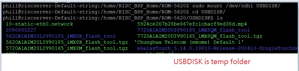
- 複製檔案到 USBDISK 中
![]()
- 解除掛載

Step 6: U 盤 插入底板的 USB port
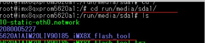
Step 7: 複製 檔案到 根目錄
cp -a 5620A1AIM20LIV90185_iMX8X_flash_tool /
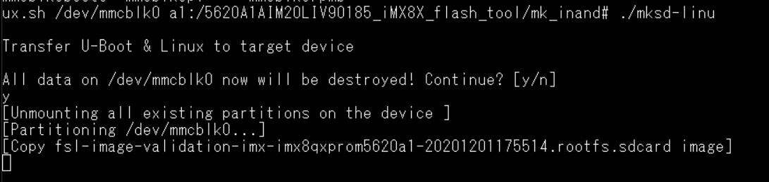
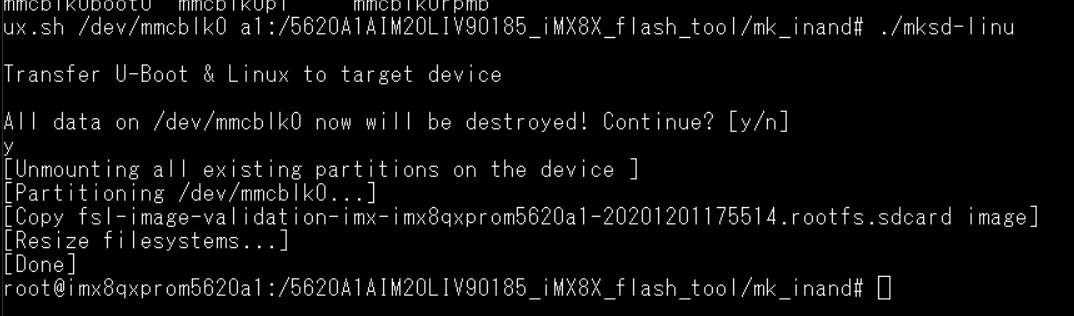
**Step 8 **使用腳本燒錄image 到 eMMC
command: ./mksd-linux.sh /dev/mmcblk0
**Step 9 **. 燒錄完畢後,移除SD Card ,
請重新開機 ,Switch 1 請調整成 1 on , 其他 off 由 eMMC 開機
Debug 串口調試 (Debug port Setting)
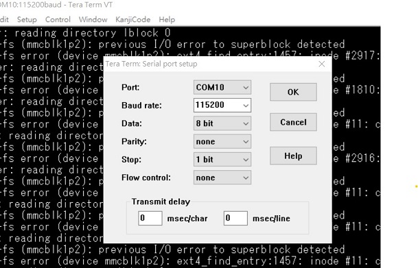
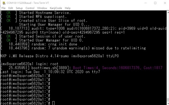
以 Tera Term 为例介绍如何使用串口调试功能
Baud Rate波特率:115200
Data 数据位:8 Parity 奇偶校验:无 Stop 停止位:1 Flow Control流控:无
Tera Term Tool
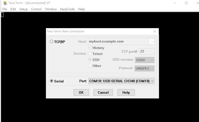
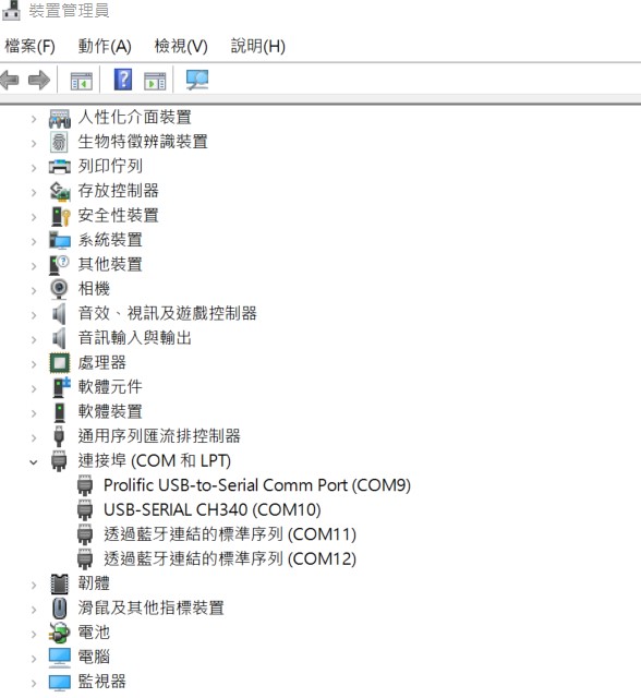
Check the Sriel port in Device Manager (查看PC端的串口号):
if you can not identify the Serial device , please check your serial driver.
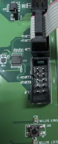
Debug port connection (串口連接)
Linux系统的基本使用(Linux System Basic Operating Method)
UUU 使用方法(USB Connection (OTG port))
Display Setting (ROM-5620)
Yocto 2.5: (Image version is 9XXXX)
U-boot Command :

setenv fdt_file xxxx.dtb
env save
boot
Display: Default support g070vw01 LVDS panel on LVDS1 LVDS
g070vw01(LVDS1)
adv-imx8mxp-rom5620-a1.dtb g150xgel05 adv-imx8qxp-rom5620-a1-lvds-chimei.dtb g215hvn01 adv-imx8qxp-rom5620-a1-lvds-dual.dtb
LVDS to HDMI(LVDS1)
adv-imx8qxp-rom5620-a1-hdmi-bridge.dtb
DSI to HDMI(LVDS1)
adv-imx8qxp-rom5620-a1-hdmi-bridge.dtb DSI auog101uan02 adv-imx8qxp-rom5620-a1-auog101uan02.dtb
Yocto 3.0: (Image version is AXXXX)
Display LVDS g070vw01 imx8mxp-rom5620-a1.dtb g150xgel05 imx8qxp-rom5620-a1-lvds-chimei.dtb g215hvn01 imx8qxp-rom5620-a1-lvds-dual.dtb LVDS to HDMI imx8qxp-rom5620-a1-hdmi-bridge.dtb DSI to HDMI imx8qxp-rom5620-a1-hdmi-bridge.dtb DSI auog101uan02 imx8qxp-rom5620-a1-auog101uan02.dtb M.2 SDIO Adjust CN43~CN48 imx8qxp-rom5620-a1-m2-sdio.dtb
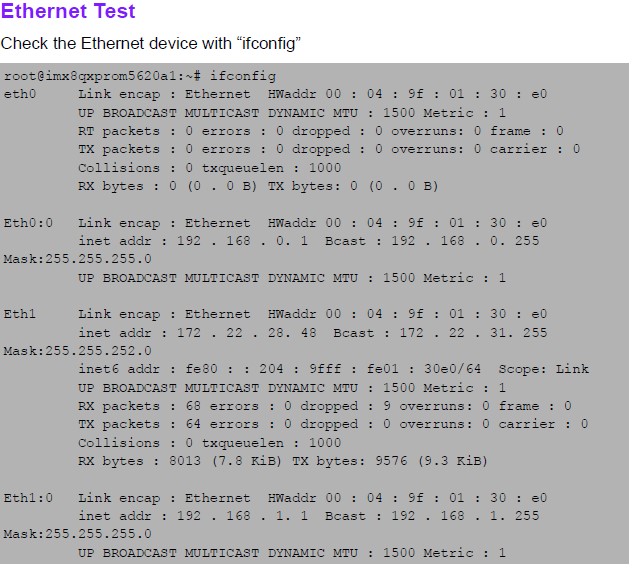
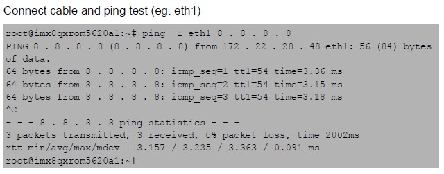
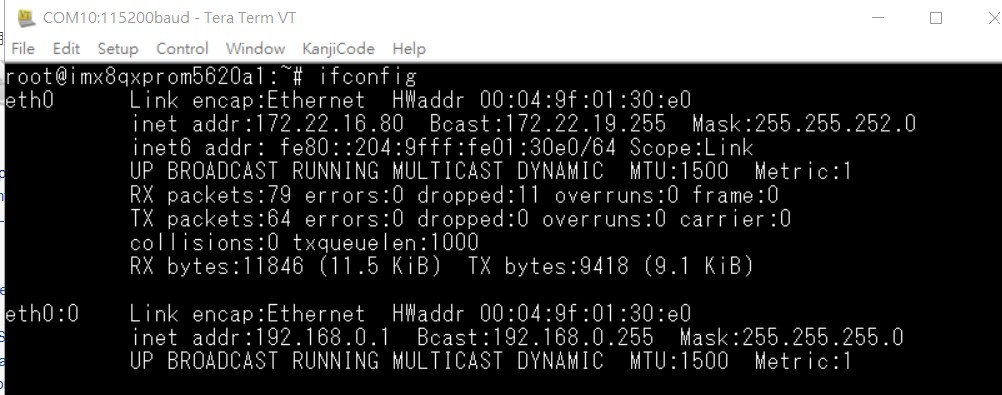
乙太網路使用方法(Ethernent Testing Method)
Command : ifconfig
Command: Ping - I eth1 8.8.8.8 or Ping - I eth0 8.8.8.8
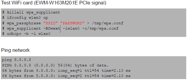
WiFi使用方法(WIFI Testing Method)
Command :

# killall wpa_supplicant
# ifconfig wlan0 up
# wpa_passphrase "SSID" "PASSWORD" > /tmp/wpa.conf
# wpa_supplicant -BDwext -iwlan0 -c/tmp/wpa.conf
# udhcpc -b -i wlan0'''

ping 8.8.8.8
PING 8.8.8.8 (8.8.8.8) 56(84) bytes of data.
64 bytes from 8.8.8.8: icmp_seq=1 ttl=54 time=2.10 ms 64 bytes from 8.8.8.8: icmp_seq=2 ttl=54 time=2.10 ms
4G使用方法(4G Testing Method)
Command:
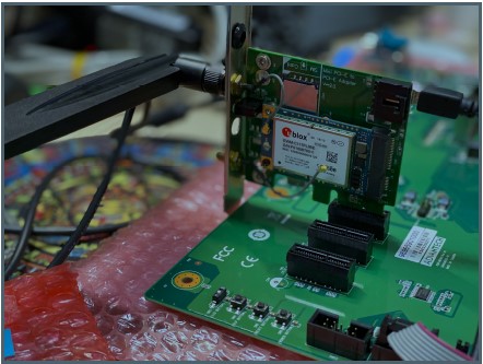
Test 4G: (EWM-C117FL06E - USB)
Step 1: Connect EWM-C117FL06E to Mini PCIE slot on 9680015491 and connect the card to CN6 PCIe_D slot on ROM-DB5901.
Step 2: Connect the antenna 1750007990-01 to the SMA (F) connector on 9680015491 and connect the IPEX connector to MT1 on EWM-C117FL06E module.
Step 3: Connect the Mini USB cable from 9680015491 to USB 2.0 Type A port on ROM-DB5901.
Step 4: Power on and execute the pppd command to connect to the network.

GPIO使用方法(GPIO Operating Method)
SMARC Pin #
| SMARC Pin # | SMARC Pin Name | CPU Ball Name | Yocto 2.5 | Yocto 3.0 | Default Direction |
|---|---|---|---|---|---|
| CPU Ball Name | Number | (Yocto 2.5) | Number | (Yocto 3.0) | Default |
| Direction | P108 | GPIO0 / CAM0_PWR# | SC_P_SPI2_CS0_LSIO_GPIO1_IO00 | 448 | 32 |
| In | P109 | GPIO1 / CAM1_PWR# | SC_P_SPI2_SCK_LSIO_GPIO1_IO03 | 451 | 35 |
| In | P110 | GPIO2 / CAM0_RST# | SC_P_SPI2_SDI_LSIO_GPIO1_IO02 | 450 | 34 |
| In | P111 | GPIO3 / CAM1_RST# | SC_P_SPI2_SDO_LSIO_GPIO1_IO01 | 449 | 33 |
| In | P112 | GPIO4 / HAD_RST# | SC_P_SPI0_CS0_LSIO_GPIO1_IO08 | 456 | 40 |
| In | P113 | GPIO5 / PWM_OUT | SC_P_SPI0_SCK_LSIO_GPIO1_IO04 | 452 | 36 |
| In | P114 | GPIO6 / TACHIN | SC_P_SPI0_SDI_LSIO_GPIO1_IO05 | 453 | 37 |
| In | P115 | GPIO7 | SC_P_MCLK_IN0_LSIO_GPIO0_IO19 | 499 | 19 |
| In | P116 | GPIO8 | SC_P_SPI0_SDO_LSIO_GPIO1_IO06 | 454 | 38 |
| In | P117 | GPIO9 | SC_P_CSI_PCLK_LSIO_GPIO3_IO00 | 384 | 96 |
| In | P118 | GPIO10 | SC_P_CSI_MCLK_LSIO_GPIO3_IO01 | 385 | 97 |
| In | P119 | GPIO11 | SC_P_CSI_EN_LSIO_GPIO3_IO02 | 386 | 98 |
| In |
Loop-back Test (Take GPIO4 and GPIO5 as examples)
Step 1: Connect GPIO4 and GPIO5
Step 2: Export GPIO interface
root@imx8qxprom5620a1 : ~# echo 456 > /sys/class/gpio/export
root@imx8qxprom5620a1 : ~# echo 452 > /sys/class/gpio/export
Step 3: Set direction
root@imx8qxprom5620a1 : ~# echo out > /sys/class/gpio/gpio1/direction
root@imx8qxprom5620a1 : ~# echo in > /sys/class/gpio/gpio2/direction
Step 4: Read value and set output value then check
root@imx8qxprom5620a1 : ~# cat /sys/class/gpio/gpio2/value
0r
oot@imx8qxprom5620a1 : ~# echo 1 > /sys/class/gpio/gpio1/value
root@imx8qxprom5620a1 : ~# cat /sys/class/gpio/gpio2/value
1
串口使用方法(Serial Port Operating Method)
RS-232 Test
CPU: SMARC pin: Linux: DB5901
SER0_UART1: SER0: /dev/ttyLP1: COM0
SER1_UART2: SER1: /dev/ttyLP2: COM1
M40_UART: SER2:: COM2
SER3_UART0: SER3: /dev/ttyLP0: COM3 (A53 Debug Port)
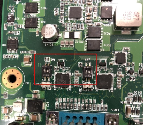
SW6/7 Setting (SW6/7設置)
RS232: 1:on 2:off
RS422: 1:on 2:on
RS485: 1:off 2:on
COM0 (CN15A): UART1 test
Loopback Test (eg. ttyLP1)
UART 1: Change SW7 jumper to switch modes. (1ON 2OFF: RS-232)
UART 1: Change CN27~CN30 jumper to (1-2 short)
# stty -F /dev/ttyLP1 -echo -onlcr 115200
# cat /dev/ttyLP1 &
# echo test > /dev/ttyLP1
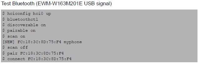
蓝牙使用方法(BlueTooth Operating Method)
Command :

$ hciconfig hci0 up
$ bluetoothctl
$ discoverable on
$ pairable on
$ scan on
[NEW] FC:18:3C:8D:75:F4 myphone
$ scan off
$ pair FC:18:3C:8D:75:F4
$ connect FC:18:3C:8D:75:F4
遠程訪問及文件傳輸(Remote Access and File Transimmion)
查看主板IP位址 ( Chech IP Address ):
Command : ifconfig
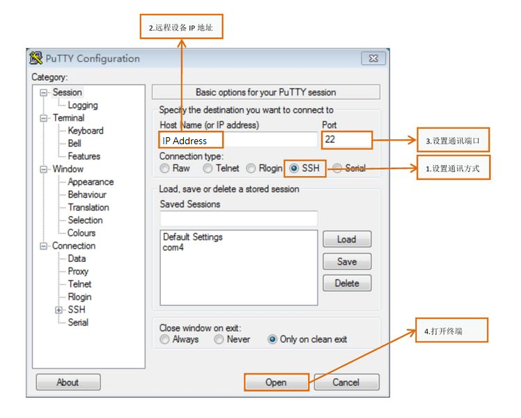
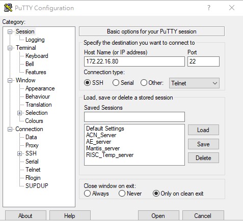
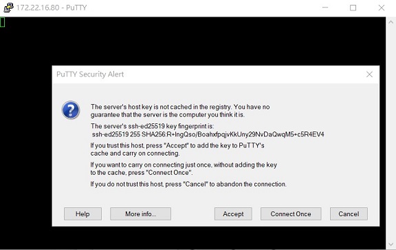
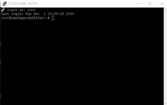
Windows下SSH访问及文件传输
SSH远程登录,以putty选择putty.exe(或者使用Xshell、SecureCRT等类似软件)
需要设置远程设备的IP、通讯端口(默认22)、通讯方式,登录后验证用户名密码
通用方法(General Method)
查看CPU温度(Check CPU Temperature)
root@imx8qxprom5620a1:/# cat /sys/devices/virtual/thermal/thermal_zone0/temp 44600

# 或者直接以度爲單位顯示 echo $[$(cat /sys/class/thermal/thermal_zone0/temp)/1000]° >>> 45°
查看CPU频率(Check CPU Frequency)
cat /sys/devices/system/cpu/cpu0/cpufreq/cpuinfo_cur_freq
>> 900000
cat /sys/devices/system/cpu/cpu0/cpufreq/cpuinfo_max_freq
>> 1200000
查看内存容量(Check Memory Capacity)
root@imx8qxprom5620a1:/# busybox free -m
total used free shared buffers cached Mem: 1794920 516080 1278840 17252 9852 80292 -/+ buffers/cache: 425936 1368984 Swap: 0 0 0
查看存储容量(Check Storage Capacity)
root@imx8qxprom5620a1:/# busybox df -h
Filesystem Size Used Available Use% Mounted on /dev/root 13.4G 1.7G 11.1G 13% / devtmpfs 395.8M 4.0K 395.8M 0% /dev tmpfs 876.4M 0 876.4M 0% /dev/shm tmpfs 876.4M 16.5M 859.9M 2% /run tmpfs 876.4M 0 876.4M 0% /sys/fs/cgroup tmpfs 876.4M 4.0K 876.4M 0% /tmp tmpfs 876.4M 280.0K 876.2M 0% /var/volatile /dev/mmcblk0p2 13.6G 1.7G 11.3G 13% /run/media/mmcblk0p2 /dev/mmcblk0p1 63.9M 23.4M 40.5M 37% /run/media/mmcblk0p1 /dev/mmcblk1p1 63.9M 23.4M 40.5M 37% /run/media/mmcblk1p1 tmpfs 175.3M 88.0K 175.2M 0% /run/user/0
root@imx8qxprom5620a1:/#
網路Ping測試(Ping Network Testing)
ping 8.8.8.8
PING 8.8.8.8 (8.8.8.8) 56(84) bytes of data.
64 bytes from 8.8.8.8: icmp_seq=1 ttl=54 time=2.10 ms 64 bytes from 8.8.8.8: icmp_seq=2 ttl=54 time=2.10 ms
設置RTC (RTC Setting)
root@imx8qxprom5620a1:/# systemctl stop ntpdate.service
root@imx8qxprom5620a1:/# date 090816072021 && hwclock -w && date
Wed Sep 8 16:07:00 UTC 2021 Wed Sep 8 16:07:00 UTC 2021
root@imx8qxprom5620a1:/# date
Wed Sep 8 16:07:06 UTC 2021
root@imx8qxprom5620a1:/#'''
Linux BSP編譯方法(Linux BSP Compile Method)
Yocto 3.0 如果有驗證上的錯誤 請使用以下的方法
### repo sync failed with Server certificate verification failed. CAfile: /etc/ssl/certs/ca-certificates.crt CRLfile: none