RSB-3710_Android_User_Guide
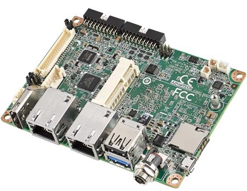
產品介紹(Product introduction )
產品特性(Product Features)
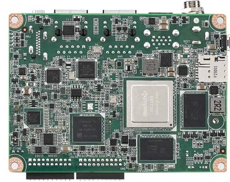
- Rockchip Arm® Cortex®-A72 RK3399 up to 1.8 GHz
- Onboard LPDDR4 2GB
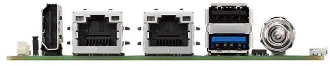
- HDMI 1920x1080 at 60Hz, 1 Dual Channel 24 bit LVDS
- 1 2-wire RS-232, 1 USB3.0, 1 USB2.0, 1 Micro SD, 1 Mic. in / Line out
- 1 mini-PCIe for 3G/4G
- UIO expansion 3 USB2.0, 8 GPIO, 2 RS232 2/2-wires UART, 1 I2C
- Supports Debian9/10 and Android7.1/10.0
- Support I/O Expansions by UIO40-Express I/O boards, please refer to page #3 for more information
產品官網連結(Product Features)
硬件接口說明(Hardware interface introduction)
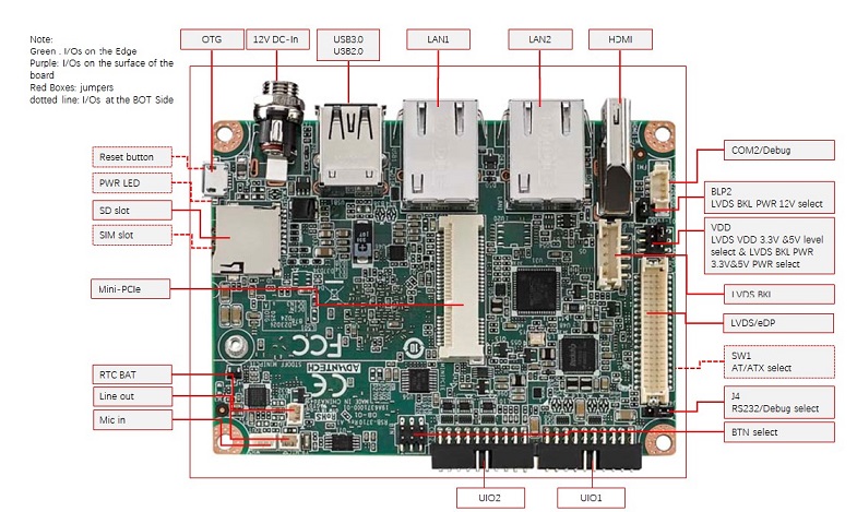
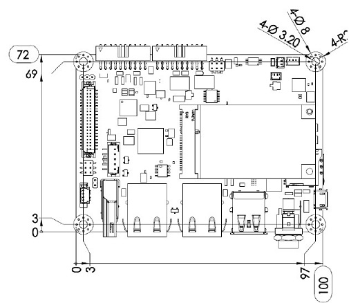
接口布局和尺寸(Layout and Sizes)
接口布局圖 Board Dimension Layout
Connector List
| BAT | RTC Battery Connector |
| HDMI | HDMI1 CONN |
| BL | LVDS BKL CONN |
| LVDS | LVDS CONN |
| LAN1 | LAN |
| LAN2 | LAN |
| MINIPCIE | MINI PCIE 52P |
| SIM | Nano SIM Card |
| AUDIO | Audio PIN Header |
| USB1 | USB CONN |
| COM2/Debug | COM2 |
| SD | SD Slot |
| OTG | USB |
| BTN | Power BTN pin header |
| RST | Reset Button |
| DCIN1 | 12V DC Jack |
| LED | LED |
| CN11 | UIO1 |
| CN12 | UIO2 |
接口引脚定義 (Pin definitions)
- [BAT](./RSB-3710_Android_User_Guide_wiki_data/BAT "BAT".md)
- [HDMI1](./RSB-3710_Android_User_Guide_wiki_data/HDMI1 "HDMI1".md)
- [BL](./RSB-3710_Android_User_Guide_wiki_data/BL "BL".md)
- [LVDS](./RSB-3710_Android_User_Guide_wiki_data/LVDS "LVDS".md)
- [LAN1, LAN2](./RSB-3710_Android_User_Guide_wiki_data/LAN1,_LAN2 "LAN1, LAN2".md)
- [MINIPCIE](./RSB-3710_Android_User_Guide_wiki_data/MINIPCIE "MINIPCIE".md)
- [SIM](./RSB-3710_Android_User_Guide_wiki_data/SIM "SIM".md)
- [Audio](./RSB-3710_Android_User_Guide_wiki_data/Audio "Audio".md)
- [USB1](./RSB-3710_Android_User_Guide_wiki_data/USB1 "USB1".md)
- [COM2/Debug](./RSB-3710_Android_User_Guide_wiki_data/COM2/Debug "COM2/Debug".md)
- [SD](./RSB-3710_Android_User_Guide_wiki_data/SD "SD".md)
- [OTG](./RSB-3710_Android_User_Guide_wiki_data/OTG "OTG".md)
- [BTN](./RSB-3710_Android_User_Guide_wiki_data/BTN "BTN".md)
- [RST](./RSB-3710_Android_User_Guide_wiki_data/RST "RST".md)
- [DCIN1](./RSB-3710_Android_User_Guide_wiki_data/DCIN1 "DCIN1".md)
- [LED](./RSB-3710_Android_User_Guide_wiki_data/LED "LED".md)
- [CN11](./RSB-3710_Android_User_Guide_wiki_data/CN11 "CN11".md)
- [CN12](./RSB-3710_Android_User_Guide_wiki_data/CN12 "CN12".md)
- [RSB-3710_Jumper List](./RSB-3710_Android_User_Guide_wiki_data/RSB-3710_Jumper_List "RSB-3710 Jumper List".md)
**机械尺寸 (**Mechanical Characteristics)
快速入门 (Quick Start)
系统下载 ( OS Download)
Note: LIV=Yocto Linux, UIV=Ubuntu, DIV=Debian, AIV=Android
LBV=BSP, LIV=Image
| Platform | Product | Image Version | Release Date | Release Version | Release notes | Image Download | BSP Download Tag | Comment |
| RK3399 | RSB-3710 | V1193 | 2021/04/20 | RTM | NA | Baidu Password:a887 Dropbox | RK3399_N7_AIV1193.xml |
-
Alpha: Basic I/O function bring up by RD;
-
Beta: Basic I/O function、performance and middleware verified by RD. Peripherals integrated;
-
GA: Beta version by QE verification;
-
RTM: Beta version by SI/Power/QE verification and pre-loaded;
Android 燒錄方法 (Flash Android image into eMMC Method)
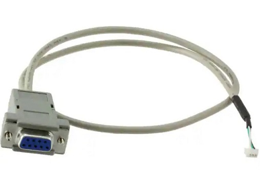
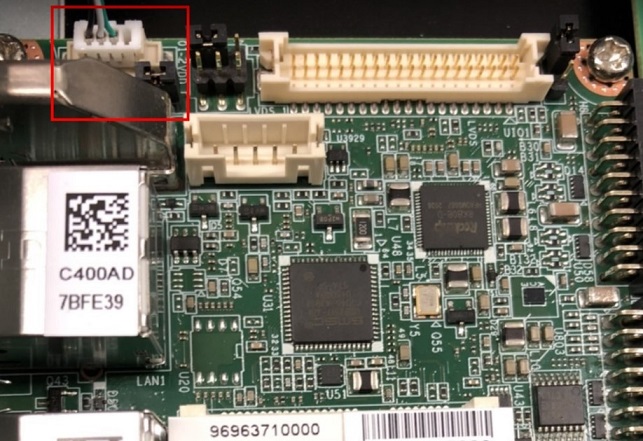
1. Prepare a mirco USB Cable and Debug Cable
mirco USB
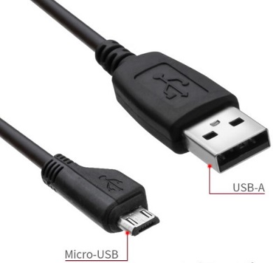
Debug Cable
- Plug the OTG Cable into RSB-3720
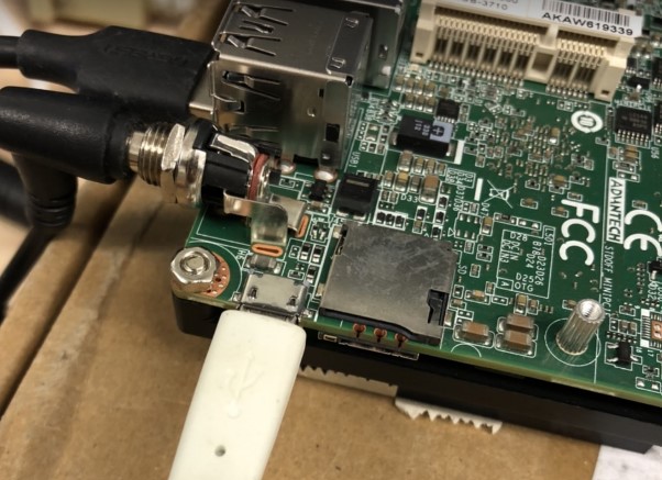
Connect Debug cable
2. 設定終端機(Set Debug Terminal)
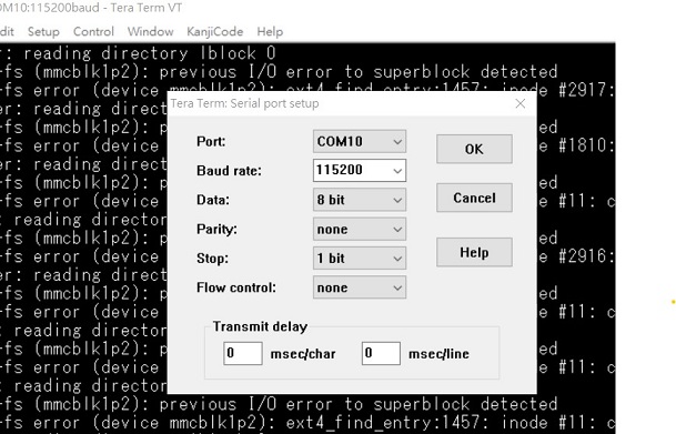
Debug 串口調試 (Debug port Setting)
Tera Term setting
   Baud Rate:115200
   Data :8
   Parity :none
   Stop :1
   Flow Control:none
Tera Term Tool
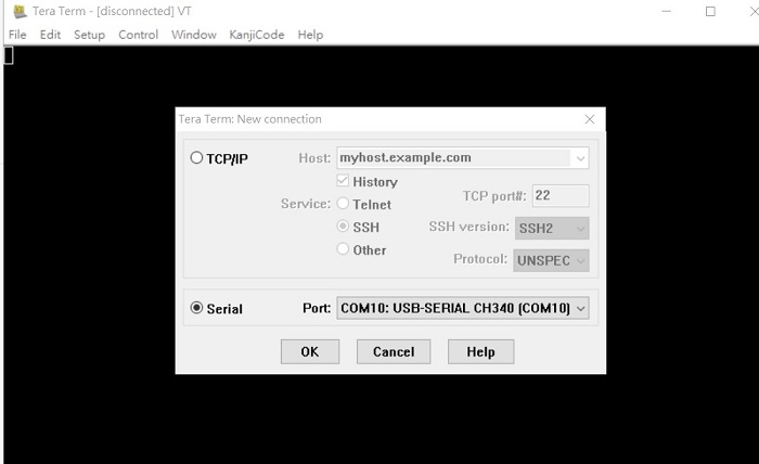
Note:
Check the Sriel port in Device Manager :
if you can not identify the Serial device , please check your serial driver.
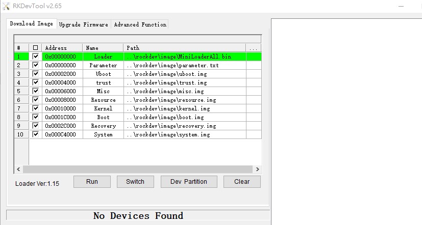
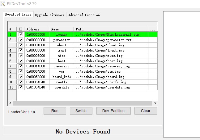
3.Open the flash tool
-
Turn on the power
-
When you see the debug message in Terminal , then press "Ctrl+C" , then log into Uboot stage
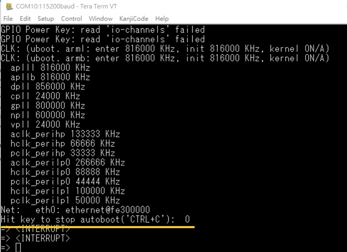
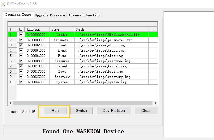
- In Uboot , please type "loader" , then the device will transfer to "Flash mode" , Android tool also will show "Found One MASKROM Device "
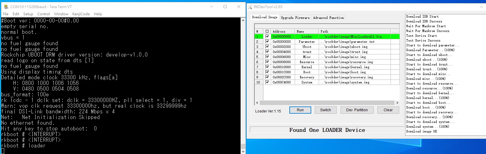
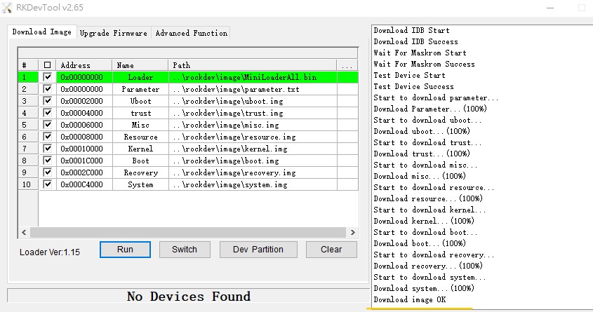
- In RKDevTool pressed "Run" , and it will flash image into eMMC.
- The flash process was finishded
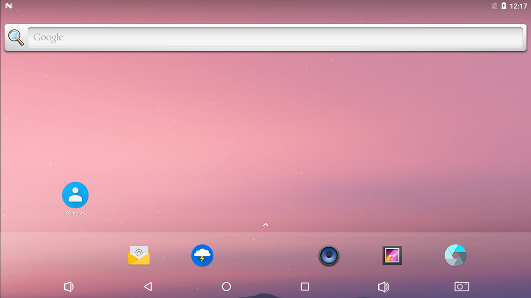
- Reboot the device , and connect with HDMI , it will show the Android Desktop.
Debian 燒錄方法 ( Flash Debian image into eMMC Method)
1. Prepare a mirco USB cable and Debug Cable
mirco USB
Debug Cable
- plugmirco USB cable into the RSB-3710 OTG port.
Connect Debug cable
3. 設定終端機(Set Debug Terminal)
Debug 串口調試 (Debug port Setting)
   Baud Rate:115200
   Data :8
   Parity :none
   Stop :1
   Flow Control:none
Tera Term Tool
Note:
查看PC端的串口号(Check the Sriel port in Device Manager) :
如果沒有找到 請先確認是否有安裝驅動(if you can not identify the Serial device , please check your serial driver.)
- Execute the Flash tool
-
Turn on the power.
-
Press "Ctrl + C", log into u-boot
- In Uboot , please type "rbrom " , the device will transfer to**"Flash mode"** , Android tool also will show "Found One MASKROM Device "
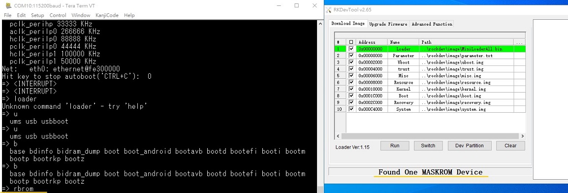
7. In RKDevTool , Press "Run" , it will flash the image into eMMC.
8. The flash process was finishded
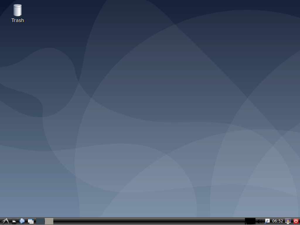
- Reboot the device , and connect with HDMI , it will show the Debian Desktop.
系统的基本使用(Linux System Basic Operating Method)
Display Setting (RSB-3710)
| lvds | lvds-g070vw01; lvds-g150xgel05; lvds-g215hvn01 |
| hdmi | hdmi-default |
| dp | dp-default |
| IN uboot | In Debian/Android |
| setenv prmry_screen hdmi-default | fw_setenv prmry_screen hdmi-default |
| setenv extend_screen edp-1920x1080 | fw_setenv extend_screen edp-1920x1080 |
| saveenv | |
| reset | reboot |
In u-boot:
=> setenv prmry_screen lvds-g070vw01
=> setenv extend_screen hdmi-default
=> saveenv
=> reset
In Linux:
~# fw_setenv prmry_screen lvds-g070vw01
~# reboot
Modify LVDS backlight PWM: (Defaul is 20KHz, New version BSP support to modify the PWM clock in u-boot from 200~20KHz)
In u-boot:
=> setenv lvds_pwm_clock 10000 (Set PWM clock to 10KHz)
In Linux:
~# fw_setenv lvds_pwm_clock 10000 (Set PWM clock to 10KHz)
~# reboot
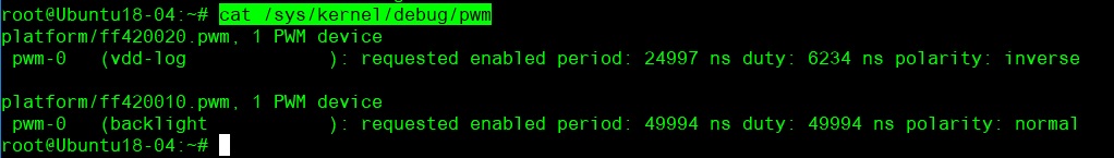
Check PWM duty sysle in Linux:
~# cat /sys/kernel/debug/pwm
乙太網路使用方法(Ethernent Testing Method)
Command : ifconfig
Command: Ping 8.8.8.8
WiFi使用方法(WIFI Testing Method)
# killall wpa_supplicant

# ifconfig wlan0 up

# wpa_passphrase "SSID" "PASSWORD" > /tmp/wpa.conf

# cat /tmp/wpa.conf

# wpa_supplicant -BDwext -iwlan0 -c/tmp/wpa.conf

# udhcpc -b -i wlan0

# ifconfig

# ping 8.8.8.8
Add DNS to /etc/resolv.conf

# cat /etc/resolv.conf

# Generated by Connection Manager
nameserver 8.8.8.8
nameserver 8.8.4.4
Now can ping google.com

# ping google.com
4G使用方法(4G Testing Method)
Ubuntu - 4G 模塊(EC-25J) 設定 ( 4G module (EC-25J) in Ubuntu system)
Ubuntu - 4G 模塊(EC-20) 設定( 4G module (EC-20) in Ubuntu system)
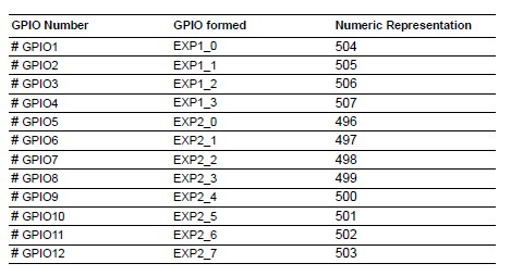
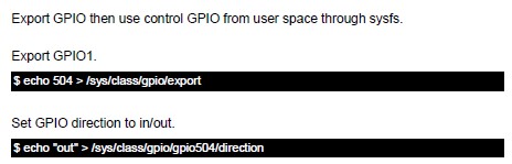
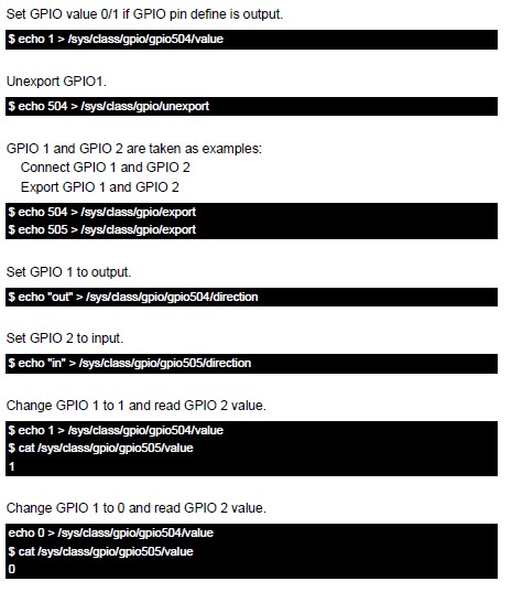
GPIO使用方法(GPIO Operating Method)
蓝牙使用方法(BlueTooth Operating Method)
# hciattach /dev/ttymxc0 bcm43xx 115200 flow

# hciconfig hci0 up

# hcitool scan# bluetoothctl

# discoverable on
#pairable on

# scan on

# scan off

# pair 84:C5:A6:D3:AF:E4

# connect 84:C5:A6:D3:AF:E4
Check BT connect info

# info 84:C5:A6:D3:AF:E4
音訊使用方法(BlueTooth Operating Method)
Line-in , Line-out, MIC
1.Line-out
Command : gplay-1.0
2.MIC
Command : arecord
Check audio codec:

# cat /proc/asound/cards
 0 [sgtl5000       ]: sgtl5000 - sgtl5000
                      sgtl5000
 1 [audiohdmi      ]: audio-hdmi - audio-hdmi
                      audio-hdmi
root@imx8mprsb3720a1:~#
   Set Mic/audio volume

# amixer set Mic 100%

# amixer set Lineout 100%

# amixer set PCM 100%

Record and playback
Example command:

# arecord –t wav –c 1 –r 44100 –d 5 /tmp/mic.wav

# aplay /tmp/mic.wav

Record from MIC:

# arecord -D plughw:0,0 -r 16000 -f S16_LE ./f-16000.wav
Recording WAVE './f-16000.wav' : Signed 16 bit Little Endian, Rate 16000 Hz, Mono

# aplay f-16000.wav
Playing WAVE 'f-16000.wav' : Signed 16 bit Little Endian, Rate 16000 Hz, Mono

Play wav file from codec:

# aplay -D plughw:0,0 file_example_WAV_10MG.wav
Playing WAVE 'file_example_WAV_10MG.wav' : Signed 16 bit Little Endian, Rate 44100 Hz, Stereo

Play wav file from HDMI:

# aplay -D plughw:1,0 file_exam
ple_WAV_10MG.wav
Playing WAVE 'file_example_WAV_10MG.wav' : Signed 16 bit Little Endian, Rate 44100 Hz, Stereo
看門狗測試 (Watch Dog Test method)
System will reboot after 1 sec

# /unit_tests/Watchdog/wdt_driver_test.out 1 2 0
遠程訪問及文件傳輸(Remote Access and File Transimmion)
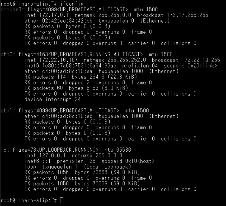
**查看主板IP位址 ( Chech IP Address ):**
Command : ifconfig
Windows下SSH访问及文件传输
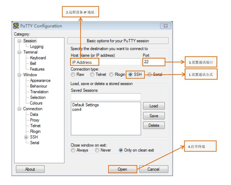
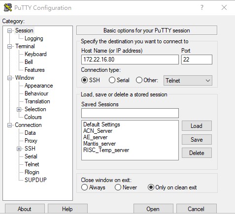
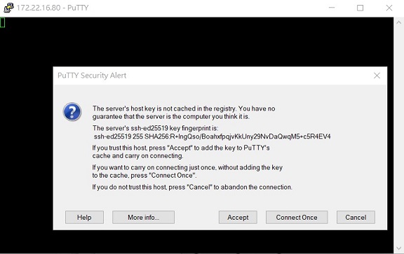
SSH Remote Log into Device
- SSH远程登录,以putty选择putty.exe(或者使用Xshell、SecureCRT等类似软件)
- 需要设置远程设备的IP、通讯端口(默认22)、通讯方式,登录后验证用户名密码
通用方法(General Method)
查看CPU温度(Check CPU Temperature)
root@linaro-alip:~# cat /sys/devices/virtual/thermal/thermal_zone0/temp
40000

# 或者直接以度爲單位顯示 echo $[$(cat /sys/class/thermal/thermal_zone0/temp)/1000]°
>> 40°
查看CPU频率(Check CPU Frequency)
cat /sys/devices/system/cpu/cpu0/cpufreq/cpuinfo_cur_freq
>> 1200000
cat /sys/devices/system/cpu/cpu0/cpufreq/cpuinfo_max_freq
>> 1800000
查看内存容量(Check Memory Capacity)
root@linaro-alip:~# busybox free -m
              total        used        free      shared  buff/cache   available
Mem:           1961         303        1096          97         561        1575
Swap:             0           0           0
root@linaro-alip:~#
查看存储容量(Check Storage Capacity)
root@linaro-alip:~# busybox df -h
Filesystem                Size      Used Available Use% Mounted on
/dev/root                 7.8G      2.8G      4.6G  37% /
devtmpfs                972.3M      8.0K    972.3M   0% /dev
tmpfs                   980.8M         0    980.8M   0% /dev/shm
tmpfs                   980.8M     16.8M    964.0M   2% /run
tmpfs                     5.0M      4.0K      5.0M   0% /run/lock
tmpfs                   980.8M         0    980.8M   0% /sys/fs/cgroup
/dev/mmcblk1p10           6.4G      3.8M      6.4G   0% /userdata
/dev/mmcblk1p7           62.6M     12.0M     47.3M  20% /oem
tmpfs                   196.2M         0    196.2M   0% /run/user/0
tmpfs                   196.2M      8.0K    196.1M   0% /run/user/1000
root@linaro-alip:~#
網路Ping測試(Ping Network Testing)
ping 8.8.8.8
PING 8.8.8.8 (8.8.8.8) 56(84) bytes of data.
64 bytes from 8.8.8.8: icmp_seq=1 ttl=54 time=2.10 ms
64 bytes from 8.8.8.8: icmp_seq=2 ttl=54 time=2.10 ms
設置RTC (RTC Setting)
Set system time to current, then write to RTC
root@linaro-alip:# date 01282022#
Fri Jan 28 20:22:00 UTC 2022
root@linaro-alip:
Restart the RTC time to system time
hwclock -s && date
root@linaro-alip:# hwclock -s && date#
Thu Jan 20 06:18:26 UTC 2022
root@linaro-alip:
如果有驗證上的錯誤 請使用以下的方法(If you got " Server certificate verification failed " message ,please follow the solution as below)
**### repo sync failed with Server certificate verification failed. CAfile: /etc/ssl/certs/ca-certificates.crt CRLfile: none
export GIT_SSL_NO_VERIFY=1
#or
git config --global http.sslverify false
============================================================**