ROM-5722 User Guide
Contents
- 1 產品介紹
- 1.1 產品特性 (Features)
- 1.2 產品官網連結 (Product information Link)
- 2 接口布局和尺寸 (Layout and Sizes)
- 2.1 ROM-5722 接口布局圖 Board Dimension Layout
- 2.2 SOM-DB2510 接口布局圖 Board Dimension Layout
- 2.3 主板内置插针式引脚排序方式 (Pin Header defination)
- 2.4 Internal I/O
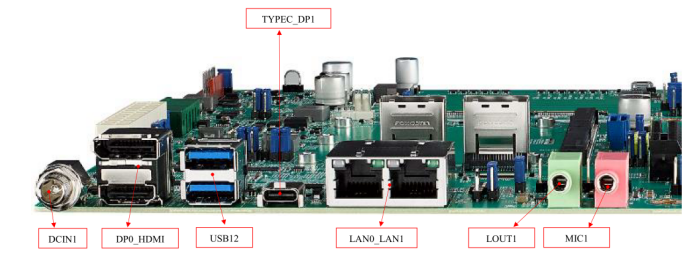
- 2.5 Rear I/O
- 2.6 Jumper 位置 (Jumper Locations)
- 2.7 LED Function List
- 2.8 Switch Settings
- 2.9 接口引脚定義 (Connector Pin definitions)
- 2.10 机械尺寸 (Mechanical Characteristics)
- 3 快速入门 (Quick Start)
- 3.1 系统下载 (OS Download)
- 3.2 Linux 燒錄方法 (Linux Flash eMMC Method)
- 3.3 Debug 串口調試 (Debug port Setting)
- 4 Linux系统的基本使用 (Linux System Basic Operating Method)
- 4.1 UUU 使用方法 (USB Connection (OTG port))
- 4.2 Display Setting (ROM-5722)
- 4.3 乙太網路使用方法 (Ethernent Testing Method)
- 4.4 WiFi使用方法 (WIFI Testing Method)
- 4.5 4G使用方法 (4G Testing Method)
- 4.6 GPIO使用方法 (GPIO Operating Method)
- 4.7 串口使用方法 (Serial Port Operating Method)
- 4.8 蓝牙使用方法 (BlueTooth Operating Method)
- 4.9 遠程訪問及文件傳輸 (Remote Access and File Transimmion)
- 4.9.1 Windows下SSH访问及文件传输
- 5 通用方法 (General Method)
- 5.1 查看CPU温度 (Check CPU Temperature)
- 5.2 查看CPU频率 (Check CPU Frequency)
- 5.3 查看内存容量 (Check Memory Capacity)
- 5.4 查看存储容量 (Check Storage Capacity)
- 5.5 網路Ping測試 (Ping Network Testing)
- 5.6 設置RTC (RTC Setting)
- 6 Linux BSP編譯方法 (Linux BSP Compile Method)
- 6.1 Yocto 5.0
- 6.2 Yocto 4.2
- 6.3 Yocto 4.0
- 6.4 Yocto 3.0
- 6.5 Build known issue
產品介紹
產品特性(Features)
- NXP Arm® Cortex®-A53 i.MX8M Plus Quad/Dual up to 1.8 GHz
- 1 x Arm Cortex-M7 core
- Onboard LPDDR4 6 GB, 4000MT/s memory
- 1 x 4 lane MIPI-CSI, 1 x Dual channel LVDS or 1 x Display Port
- 4 x USB2.0, 1 x USB 2.0 OTG, 4 x UART, 5 x I2C, 14 x GPIO, 1 x PCIe3.0, 2 x Gigabit LAN, 2 x CAN-FD
- Neural network accelerator up to 2.3 TOPS
- Supports Yocto Linux and Android
產品官網連結(Product information Link)
接口布局和尺寸(Layout and Sizes)
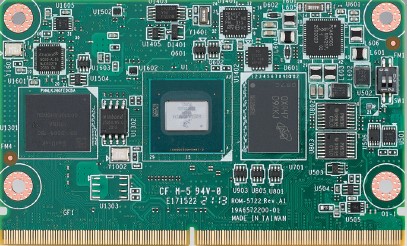
ROM-5722 接口布局圖 Board Dimension Layout

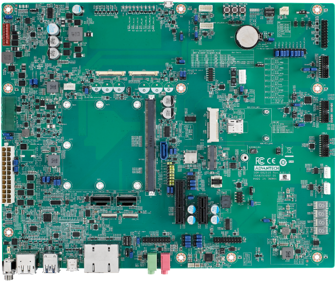
SOM-DB2510 接口布局圖 Board Dimension Layout
主板内置插针式引脚排序方式 (Pin Header defination)
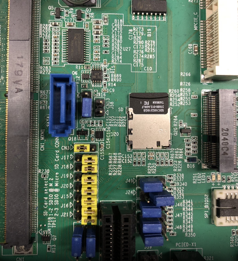
Internal I/O
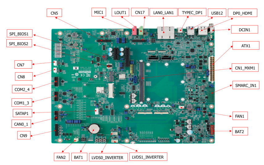
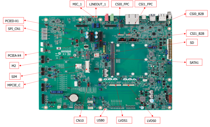
| Label | Function | Label | Function |
|---|---|---|---|
| ATX1 | ATX Connector | FAN1 | Smart Fan Connector |
| SMARC_IN1 | Wide Range Input Power Connector (3V~5.25V) | FAN2 | System Fan Connector |
| DCIN1 | DCIN connector | CAN0_1 | CAN Bus Connector |
| DP0_HDMI | DP & HDMI Connector | USB0 | USB OTG Connector |
| USB12 | USB 2.0 port1~2 & USB 3.0 port0 Connector | COM1_3 | COM Port Port1,3 Connector |
| TYPEC_DP1 | Type-C Connector | COM2_4 | COM Port Port2,4 Connector |
| LAN0_LAN1 | LAN0 & LAN1 Connector | CN8 | I2C connector for I2C_PM |
| LOUT1 | Line Out Connector | CN7 | I2C Connector for I2C_GP |
| MIC1 | MIC1 Connector | CN10 | eSPI Pin Header |
| CN1_MXM1 | SMARC Connector | SATAP1 | SATA Power Connector |
| PCIEA-X4 | PCIe x4 Connector | CSI0_B2B | MIPI B2B Connector for 2M Camera |
| SATA1 | SATA Port0 Connector | CSI1_B2B | MIPI B2B Connector for 8M & 13M Camera |
| PCIED-X1 | PCIe x1 Connector | SPI_BIOS1 | Carrier Board BIOS Socket (SOIC) |
| M2 | M.2 Key-E Connector | BAT1 | Coin battery holder |
| MPCIE_C | Mini PCIe Connector | BAT2 | Smart battery Connector |
| SIM | SIM card Connector | LINEOUT_1 | I2S Headphone Connector |
| LVDS1 | LVDS1 Connector | MIC_1 | I2S MIC In Connector |
| LVDS0 | LVDS0 Connector | CSI1_FPC | MIPI FPC Connector for 8M & 13M Camera |
| LVDS1_INVERTER | LVDS1 Invertor Connector | CSI0_FPC | MIPI FPC Connector for 2M Camera |
| LVDS0_INVERTER | LVDS0 Invertor Connector | CN5 | I2S2 Connector |
| SPI_BIOS2 | Carrier Board BIOS Socket (QFN) | CN17 | I2S0 Connector |
| SD | SD Card Connector |
Rear I/O
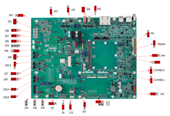
Jumper 位置( Jumper Locations)
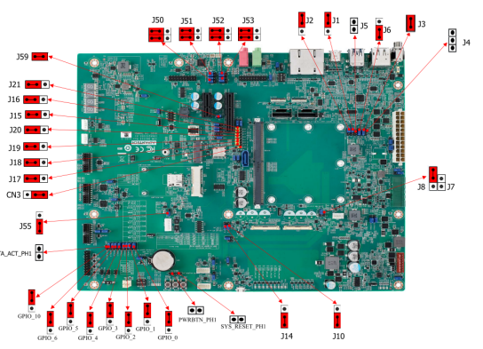
| Lable | Function | Lable | Function |
|---|---|---|---|
| BTN3 | Sleep Button | J14 | EDP1/LVDS1 Hot-Plug Detect Selection Header |
| BTN1 | Power Button | J56 | Standby Voltage Control Header |
| BTN2 | Reset Button | J44 | Module +3.3V/+5V Power Selection Header |
| SW4 | BOOT SELECT Switch | PSON1 | AT/ATX Selection Header |
| LID1 | LID Switch | SPI_CN1 | SPI Header |
| J30 | Enable Battery Low# Header | CN14 | For CAN Bus port0 Terminal Resistor |
| M2E_DISABLE_N1 | M.2 Wireless Disable | CN15 | For CAN Bus port1 Terminal Resistor |
| J29 | SMB Alert Enable Header | J3/J4 | DP0 EQ0 Selection |
| CN9 | Header For GPIO Test | J5/J6 | DP0 EQ1 Selection |
| J7/J8 | LVDS0 Power Selection Header | J58 | PCIE_B_CKREQ# Selection |
| J11/J12 | LVDS1 Power Selection Header | J59 | PCIE_A_CKREQ# Selection |
| J9 | LVDS0 Inverter Power Selection Heade | GPIO_0 | GPIO0/CAM0_PWR# Selection |
| J10 | EDP0/LVDS0 Hot-Plug Detect Selection Header | GPIO_1 | GPIO1/CAM1_PWR# Selection |
| J26 | HDA/I2S Selection Header | GPIO_2 | GPIO2/CAM0_RST# Selection |
| J1 | DP1/HDMI1 Select | GPIO_3 | GPIO3/CAM1_RST# Selection |
| J13 | LVDS1 Inverter Power Selection Header | GPIO_4 | GPIO4/HDA_RST# Selection |
| J31 | Clear CMOS Header | GPIO_5 | GPIO5/PWM_OUT Selection |
| J25 | SPI Power Header | GPIO_6 | GPIO6/TACHIN Selection |
| SW1 | COM1 mode Select | SATA_ACT_PH1 | SATA act# Header |
| SW2 | COM3 mode Select | PWRBTN_PH1 | Power button Header |
| J41 | Core Power Voltage Control Header | SYS_RESET_PH1 | Reset button Header |
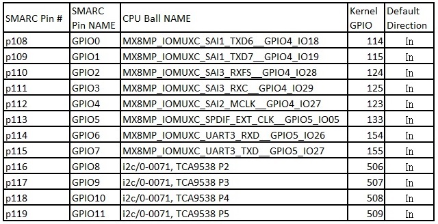
| J2 | DDI1 AUX/DDC Selection |
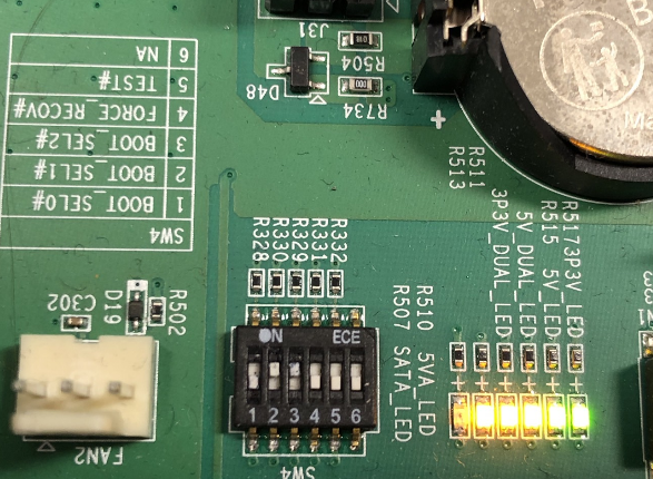
LED Function List
| Location | Function |
|---|---|
| MODULE_VIN_LED1 | WDT_TIME_OUT# Indicate |
| MODULE_5V_LED | Module 5V Indicate |
| MODULE_VIN_LED | Module +V_MOD_IN Indicate |
| RESET_OUT_LED | RESET_OUT Indicate |
| RESET_OUT_LED | CARRIER_STBY Indicate |
| CARRIER_PWR_ON_LED | CARRIER_PWR_ON Indicate |
| MODULE_3P3V_LED | Module 3.3V Indicate |
| 3P3V_LED | Carrier Board +V3.3 Indicate |
| 5V_LED | Carrier Board +V5 Indicate |
| 5V_DUAL_LED | Carrier Board +V5SB Indicate |
| 3P3V_DUAL_LED | Carrier Board +V3.3SB Indicate |
| 5VA_LED | Carrier Board +V5D_MOD Indicate |
| SATA_LED | SATA Indicate |
| SOM_LED | SOM BOM Indicate |
| RISC_LED | RISC BOM Indicate |
Switch Settings
- SW4 (Boot Select/Force Recovery/Test Switches)
- LID1 (LID Button Enable/Disable Switches)
- SW5 (LAN CONN LED Pull High Switches)
- SW1 (COM0 Settings)
- SW2 (COM2 Settings)
- SW3 (I2S Clock Settings)
- M2E_DISABLE_N1 (M.2 Wireless Disable Switch)
接口引脚定義 (Connector Pin definitions)
- ATX1 Pin Connector
- SMARC_IN1 Pin Connectors
- BAT1 RTC Battery Connectors
- DCIN1 DC-IN Power Connectors
- CAN0_1 CAN Bus Connectors
- CN9 GPIO Headers
- COM2_4 COM Port2&4 Connectors
- COM1_3 COM Port1&3 Connectors
- CN10 ESPI Headers
- LVDS0 LVDS Connectors
- LVDS0_INVERTER LVDS INVERTER Connectors
- LVDS1 LVDS Connectors
- LVDS1_INVERTER LVDS INVERTER Connectors
- CN7 I2C_GP Connectors
- SPI_CN1 SPI Connectors
- SATAP1 SATA PWR Connectors
- CSI0_FPC Connectors
- CSI1_FPC Connectors
- CN5 I2S2 Connectors
- CN17 I2S0 Connectors
- PWRBTN_PH1 PWRBTN Pin Headers
- SYS_RESET_PH1 SYS RESET Pin Headers
- SATA_ACT_PH1 SATA ACT# Pin Headers
- J32 Power LED Pin Headers
- J30 BATLOW Pin Headers
- J29 SMBUS Alert Pin Headers
- J41 Core Power Controls
- PSON1 ATX/AT Mode Selection
- J56 Standby Power Controls
- J44 Module Power Settings
- J7,J8 LVDS0 Power Selection
- J9 LVDS0 Inverter Power Selection
- J11,J12 LVDS1 Power Selection
- LVDS1 Inverter Power Selection
- EDP0/LVDS0 HPD Selection
- J14 EDP1/LVDS1 HPD Selection
- CN14 CAN0 Terminal Resistor Selection
- CN15 CAN1 Terminal Resistor Selection
- J2 DDI1 AUX/DDC Selection
- J1 DP1/HDMI1 Selection
- J58 PCIE_B_CKREQ# Selection
- J59 PCIE_A_CKREQ# Selection
- J31 Clear CMOS
- J25 +V1.8M_SPI Power Jumpers
- GPIO_0 GPIO0 Settings
- GPIO_1 GPIO1 Settings
- GPIO_2 GPIO2 Settings
- GPIO_3 GPIO3 Settings
- GPIO_4 GPIO4 Settings
- GPIO_5 GPIO5 Settings
- GPIO_6 GPIO6 Settings
- J26 HDA/I2S Selection
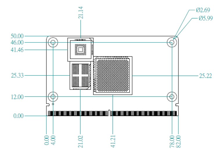
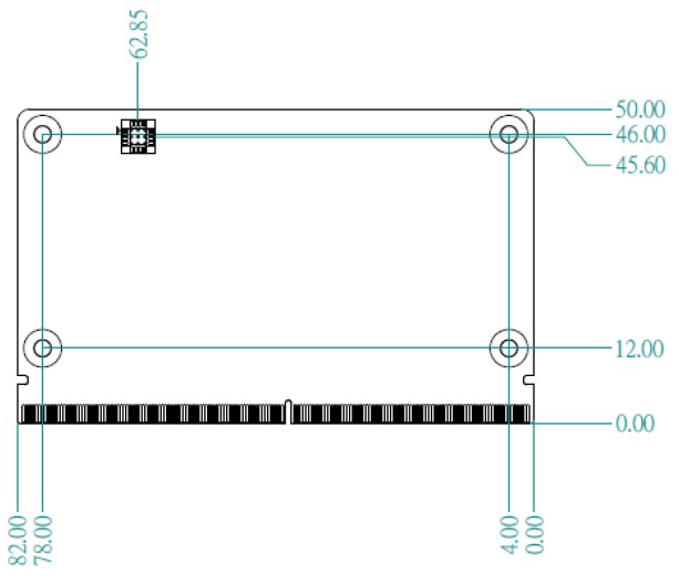
机械尺寸 (Mechanical Characteristics)
ROM-5722
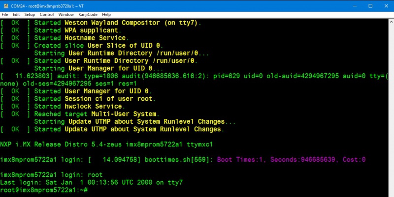
快速入门 (Quick Start)
系统下载 (OS Download)
- Linux系统 (Linux OS)
Yocto 3.0: IoTGateway/BSP/Linux/iMX8/OS Support List 3.0
Linux 燒錄方法 (Linux Flash eMMC Method)
使用Flash tool 燒錄鏡像到eMMC (Flash image into eMMC by Flash Tools)
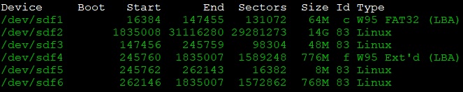
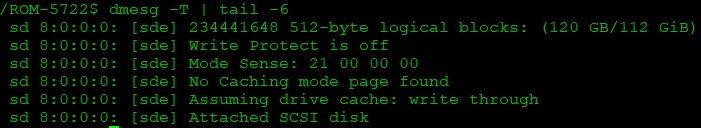
Step0: 檢查SD卡在Linux 環境的代號 (check SD card symbol in Linux system)
![]()
Step1: 創造一張可開機的SD 卡 (Create a bootable SD card)
Command:
sudo dd if=5722A1AIM30LIVA0271_iMX8MP_6G_2021-06-19.img of=/dev/sdf bs=1M conv=fsync status=progress
Step2: 將可開機的SD 卡插入底板SD卡卡槽 (Plug the SD card into Carrier board's SD card slot)
Step4: 確認開機選擇指撥開關
- SD 卡開機模式: (2, 3:on, others off)
- eMMC 開機模式: (1: on, others off)
Step3: 打開電源 和 終端機 (Turn on the Power & Terminal)

Step4: 解壓縮flash tools 檔案,並複製到U盤中 (Unzip the flash tools file, then copy to USB Disk)
解壓縮 (Unzip the file)
複製檔案到U盤中 (Copy the flash file to USB Disk)
-
插入U盤到你的Ubuntu 電腦上 (Plug the USB Disk into your Linux PC)
-
檢視U盤在Ubuntu 系統代號 (Check the USB Disk's symbol in Ubuntu System)
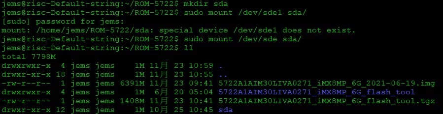
- 掛載U盤在Ubuntu 系統中 (Mount the USB Disk in Ubuntu)
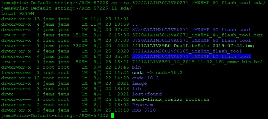
- 複製檔案到U盤 (Copy the file to USB disk)
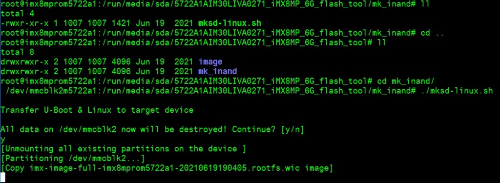
- 將U盤連接到ROM-5722系統, 進入flash tool下的mk_inand資料夾, 執行指令
./mksd-linux.sh /dev/mmcblk2燒錄image到eMMC (Connect USB Disk to ROM-5722 system, browse to mk_inand folder and execute flash shell script./mksd-linux.sh /dev/mmcblk2)
| ROM-5722 | |
|---|---|
| SD card | /dev/mmcblk1 |
| eMMC | /dev/mmcblk2 |
- 切換開機switch 1:on 2,3,4,5,6:off來設定成從eMMC開機 (Change boot switch to "1:on 2,3,4,5,6:off" to boot from eMMC. Reboot system).
Debug 串口調試 (Debug port Setting)
Debug port output:
| ROM-5722 CPU | ROM-5722 golden finger | DB5901 | DB2510 |
|---|---|---|---|
| UART1 | SER2 | CN15B down | COM3 |
| UART2: A53 | SER3 | COM3 | COM4 |
| UART3 | SER0 | CN15A up | COM1 |
| UART4: M7 | SER1 | COM1 | COM2 |
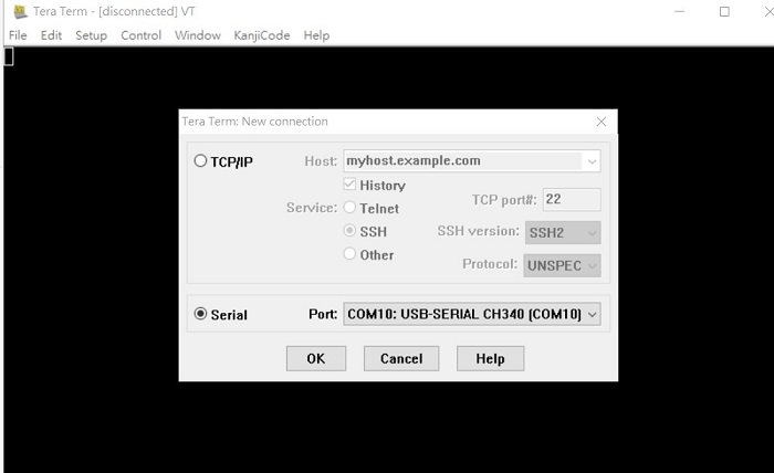
以 Tera Term 为例介绍如何使用串口调试功能
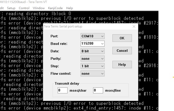
Baud Rate波特率:115200
Data 数据位:8
Parity 奇偶校验:无
Stop 停止位:1
Flow Control流控:无
Tera Term Tool
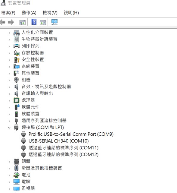
Check the Serial port in Device Manager (查看PC端的串口号):
if you can not identify the Serial device, please check your serial driver.
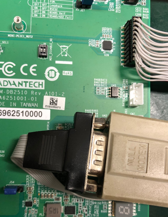
Debug port connection (串口連接)
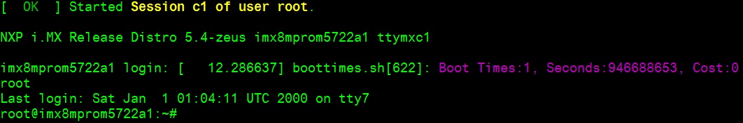
Log into Terminal Tool (进入串口调试终端):

Linux系统的基本使用(Linux System Basic Operating Method)
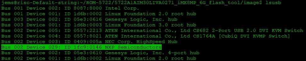
UUU 使用方法(USB Connection (OTG port))
Download uuu tool from (ADV v20210429 · ADVANTECH-Corp/uuu · GitHub) or in the folder.
uuu (Universal Update Utility) for nxp imx chips -- libuuu_1.3.191-67-ga9523ec
The "imx-boot-imx8mprom5722a1-6G.bin-flash_evk" file be included in 5722A1AIM30LIVA0XXX_iMX8MP_6G_misc.tgz. XXX is the version.
Connect USB cable to USB OTG port.
Change boot switch to "4:on 1,2,3,5,6:off" to boot from force recovery mode.
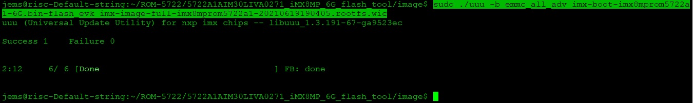
Type command below to flash eMMC:
Display Setting (ROM-5722)
Ex:
setenv fdtfile imx8mp-rom5722-a1-lvds0-auo.dtb
U-boot Command:
- Display
- HDMI (default)
- imx8mp-rom5722-a1.dtb
- LVDS
- g070vw01 (LVDS0) + HDMI
- imx8mp-rom5722-a1-lvds0-auo.dtb
- g070vw01 (LVDS1) + HDMI
- imx8mp-rom5722-a1-lvds1-auo.dtb
- g215hvn01 (DUAL LVDS) + HDMI
- imx8mp-rom5722-a1-lvds-dual.dtb
- g070vw01 (LVDS0) + HDMI
- DSI
- adv7535 (DSI to HDMI) + HDMI
- imx8mp-rom5722-a1-adv7535.dtb
- auog101uan02 (DSI) + HDMI
- imx8mp-rom5722-a1-auog101uan02.dtb
- adv7535 (DSI to HDMI) + HDMI
- HDMI (default)
- Camera
- OV5640 (default)
- imx8mp-rom5722-a1.dtb
- Basler camera
- imx8mp-rom5722-a1-basler.dtb
- OV5640 (default)
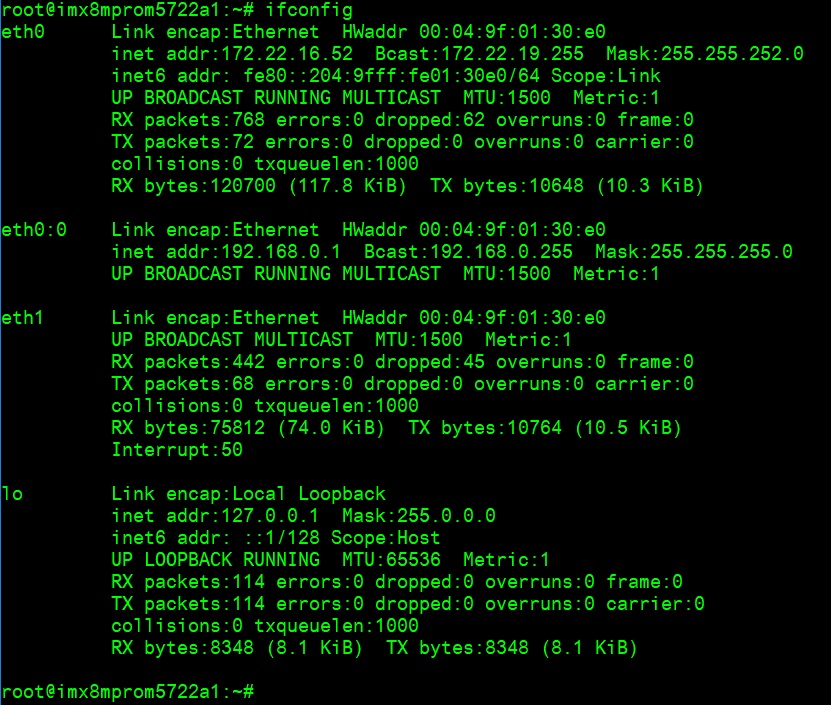
乙太網路使用方法(Ethernent Testing Method)
Command: ifconfig
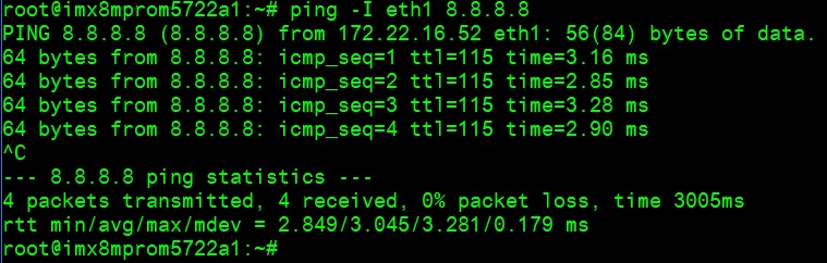
Command: Ping -I eth1 8.8.8.8 or Ping -I eth0 8.8.8.8
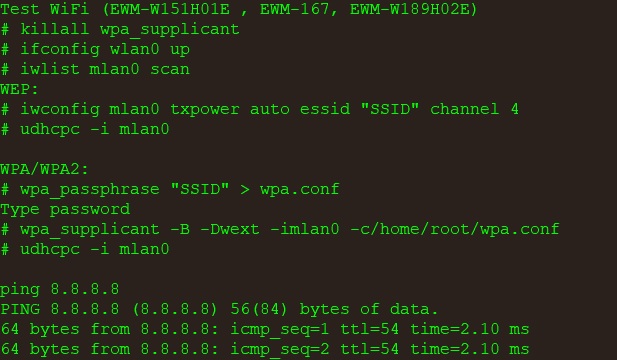
WiFi使用方法(WIFI Testing Method)
# killall wpa_supplicant
# ifconfig wlan0 up
# iwlist mlan0 scan

WEP:
# iwconfig mlan0 txpower auto essid "SSID" channel 4
# udhcpc -i mlan0

WPA/WPA2:
# wpa_passphrase "SSID" > wpa.conf
Type password
# wpa_supplicant -B -Dwext -imlan0 -c/home/root/wpa.conf
# udhcpc -i mlan0

ping 8.8.8.8
PING 8.8.8.8 (8.8.8.8) 56(84) bytes of data.
64 bytes from 8.8.8.8: icmp_seq=1 ttl=54 time=2.10 ms
64 bytes from 8.8.8.8: icmp_seq=2 ttl=54 time=2.10 ms

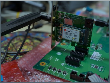
4G使用方法(4G Testing Method)
Command:
Test 4G: (EWM-C117FL06E - USB)
Step 1: Connect EWM-C117FL06E to Mini PCIE slot on 9680015491 and connect
the card to CN6 PCIe_D slot on ROM-DB5901.
Step 2: Connect the antenna 1750007990-01 to the SMA (F) connector on
9680015491 and connect the IPEX connector to MT1 on EWM-C117FL06E module.
Step 3: Connect the Mini USB cable from 9680015491 to USB 2.0 Type A port on
ROM-DB5901.
Step 4: Power on and execute the pppd command to connect to the network.
GPIO使用方法(GPIO Operating Method)
GPIO pin:
Loop-back Test (Take GPIO0 and GPIO2 as examples)

Step 1: Connect GPIO0 and GPIO2
Step 2: Export GPIO interface

root@imx8mprom5722a1: ~# echo 114 > /sys/class/gpio/export
root@imx8mprom5722a1: ~# echo 124 > /sys/class/gpio/export

Step 3: Set direction

root@imx8mprom5722a1: ~# echo out > /sys/class/gpio/gpio1/direction
root@imx8mprom5722a1: ~# echo in > /sys/class/gpio/gpio2/direction

Step 4: Read value and set output value then check

root@imx8mprom5722a1: ~# cat /sys/class/gpio/gpio2/value
0
root@imx8mprom5722a1: ~# echo 1 > /sys/class/gpio/gpio1/value
root@imx8mprom5722a1: ~# cat /sys/class/gpio/gpio2/value
1
串口使用方法(Serial Port Operating Method)
RS-232 Test
CN15上 (SER0/UART3): /dev/ttymxc2
CN15 下 (SER2/UART1): /dev/ttymxc0
COM 3 (A53 debug/SER3/UART2): /dev/ttymxc1
COM 1 (M7 debug/SER1/UART4): /dev/ttymxc3
SW7 Setting (SW7設置)
MODE1  MODE0
  0      0    LOOPBACK
  0      1    RS232
  1      0    RS485
  1      1    RS422
Loopback test (eg. ttymxc0) Connect loopback test tool
stty -F /dev/ttymxc0 115200
stty -F /dev/ttymxc0 -echo
cat /dev/ttymxc0 &
echo test > /dev/ttymxc0
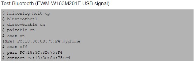
蓝牙使用方法(BlueTooth Operating Method)
$ hciconfig hci0 up
$ bluetoothctl
$ discoverable on
$ pairable on
$ scan on
[NEW] FC:18:3C:8D:75:F4 myphone
$ scan off
$ pair FC:18:3C:8D:75:F4
$ connect FC:18:3C:8D:75:F4
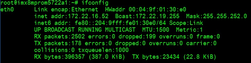
遠程訪問及文件傳輸(Remote Access and File Transimmion)
查看主板IP位址 ( Check IP Address ):
Command : ifconfig
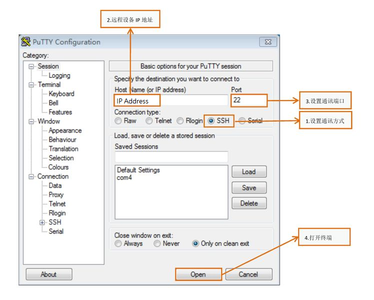
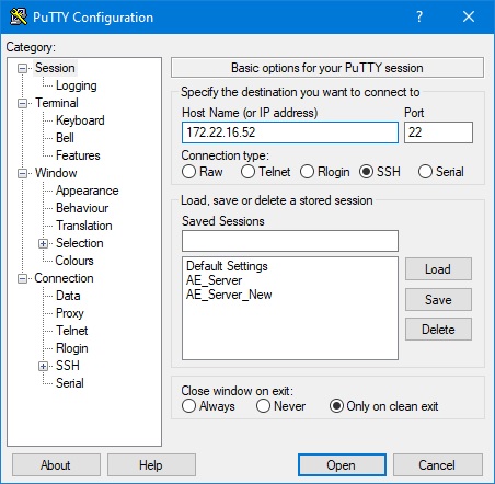
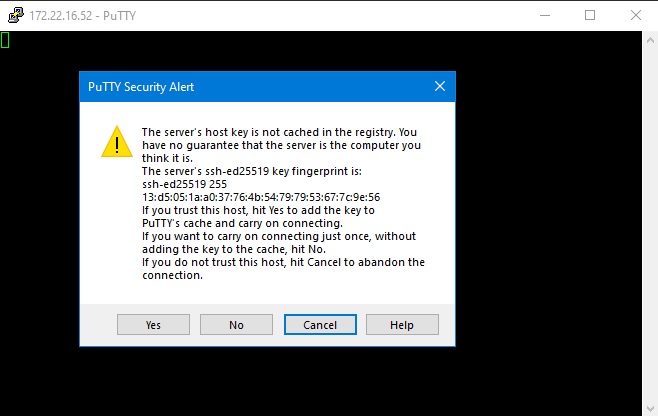
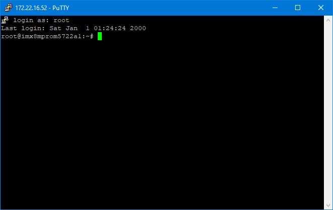
Windows下SSH访问及文件传输
SSH Remote Log into Device
- SSH远程登录,以putty选择putty.exe(或者使用Xshell、SecureCRT等类似软件)
- 需要设置远程设备的IP、通讯端口(默认22)、通讯方式,登录后验证用户名密码
通用方法(General Method)
查看CPU温度(Check CPU Temperature)
root@imx8mprom5722a1:/# cat /sys/devices/virtual/thermal/thermal_zone0/temp
44600

# 或者直接以度爲單位顯示
echo $[$(cat /sys/class/thermal/thermal_zone0/temp)/1000]°
>>> 45°
查看CPU频率(Check CPU Frequency)
cat /sys/devices/system/cpu/cpu0/cpufreq/cpuinfo_cur_freq
>> 900000
cat /sys/devices/system/cpu/cpu0/cpufreq/cpuinfo_max_freq
>> 1200000
查看内存容量(Check Memory Capacity)
root@imx8mprom5722a1:~# busybox free -m
              total        used        free      shared  buff/cache   available
Mem:        6002516      402812     5505276       26668       94428     5493888
Swap:             0           0           0
查看存储容量(Check Storage Capacity)
root@imx8mprom5722a1:~# busybox df -h
Filesystem                Size      Used Available Use% Mounted on
/dev/root                14.1G      3.6G      9.8G  27% /
devtmpfs                  2.4G      4.0K      2.4G   0% /dev
tmpfs                     2.9G         0      2.9G   0% /dev/shm
tmpfs                     2.9G     25.1M      2.8G   1% /run
tmpfs                     2.9G         0      2.9G   0% /sys/fs/cgroup
tmpfs                     2.9G         0      2.9G   0% /tmp
tmpfs                     2.9G    268.0K      2.9G   0% /var/volatile
/dev/mmcblk2p1           83.0M     29.6M     53.5M  36% /run/media/mmcblk2p1
tmpfs                   586.2M      4.0K    586.2M   0% /run/user/0
/dev/mmcblk1p1           83.0M     29.6M     53.5M  36% /run/media/mmcblk1p1
/dev/mmcblk1p2           14.2G      3.6G     10.0G  26% /run/media/mmcblk1p2
root@imx8mprom5722a1:~#
網路Ping測試(Ping Network Testing)
ping 8.8.8.8
PING 8.8.8.8 (8.8.8.8) 56(84) bytes of data.
64 bytes from 8.8.8.8: icmp_seq=1 ttl=54 time=2.10 ms
64 bytes from 8.8.8.8: icmp_seq=2 ttl=54 time=2.10 ms
設置RTC (RTC Setting)
root@imx8mprom5722a1:~# systemctl stop ntpdate.service
root@imx8mprom5722a1:~# date 090816072021 && hwclock -w && date
Wed Sep  8 16:07:00 UTC 2021
Tue Nov 23 07:38:50 UTC 2021
root@imx8mprom5722a1:~# date
Tue Nov 23 07:38:56 UTC 2021
root@imx8mprom5722a1:~#
Add Patch in linux-imx_6.1.bb file
SRC_URI:append:imx8qmrom5722a1 += " file://panel_gpi4.patch"
Build known issue
如果有驗證上的錯誤 請使用以下的方法
repo sync failed with Server certificate verification failed
CAfile: /etc/ssl/certs/ca-certificates.crt CRLfile: none
ERROR: gstreamer1.0 do_unpack failure (click to expand)
ERROR: gstreamer1.0-1.14.4.imx-r0 do_unpack: Fetcher failure: Fetch command ... git submodule update --init --recursive failed with exit code 1

fatal: unable to access 'https://anongit.freedesktop.org/git/gstreamer/common.git/':
server certificate verification failed. CAfile: /etc/ssl/certs/ca-certificates.crt CRLfile: none

Failed to clone 'common' a second time, aborting

ERROR: gstreamer1.0-1.14.4.imx-r0 do_unpack: Function failed: base_do_unpack
ERROR: Task (.../gstreamer1.0_1.14.imx.bb:do_unpack) failed with exit code '1'

ERROR: gstreamer1.0-plugins-base-1.14.4.imx-r0 do_unpack: Function failed: base_do_unpack
ERROR: Task (.../gstreamer1.0-plugins-base_1.14.imx.bb:do_unpack) failed with exit code '1'
nnshark error
https://community.nxp.com/t5/i-MX-Processors/Yocto-3-3-5-10-72-BSP-Build-Fail/m-p/1487902