ROM-5721 User Guide
Contents
- 1 產品介紹 (Product introduction)
- 1.1 產品特性 (Product Features)
- 1.2 產品官網連結
- 2 硬件接口說明 (Hardware interface introduction)
- 2.1 接口布局和尺寸 (Layout and Sizes)
- 2.2 ROM-5721 接口布局圖 Board Dimension Layout
- 2.3 主板内置插针式引脚排序方式 (Pin Header defination)
- 2.4 Internal I/O
- 2.5 Rear I/O
- 2.6 接口引脚定義 (Pin definitions)
- 2.7 机械尺寸 (Mechanical Characteristics)
- 3 快速入门 (Quick Start)
- 3.1 系统下载 (OS Download)
- 3.2 Linux 燒錄方法 (Linux Flash eMMC Method)
- 3.3 Debug 串口調試 (Debug port Setting)
- 4 Linux系统的基本使用 (Linux System Basic Operating Method)
- 4.1 UUU 使用方法 (USB Connection (OTG port))
- 4.2 Display Setting (ROM-5721)
- 4.3 乙太網路使用方法 (Ethernent Testing Method)
- 4.4 WiFi使用方法 (WIFI Testing Method)
- 4.5 串口使用方法 (Serial Port Operating Method)
- 4.6 蓝牙使用方法 (BlueTooth Operating Method)
- 4.7 遠程訪問及文件傳輸 (Remote Access and File Transimmion)
- 5 通用方法 (General Method)
- 6 Linux BSP編譯方法 (Linux BSP Compile Method)
- 7 Build known issue
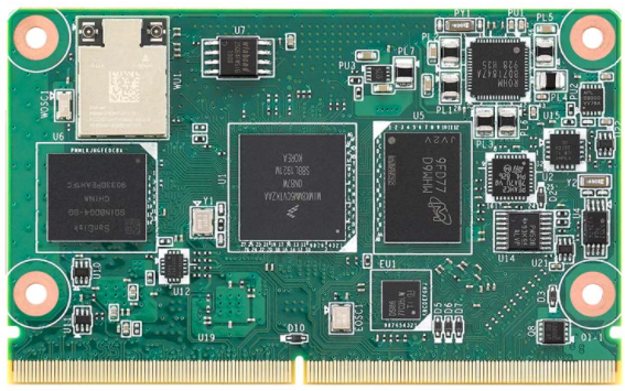
產品介紹(Product introduction)
產品特性(Product Features)
- NXP i.MX 8M Mini processor with up to 4 Arm Cortex A53 cores
- 1 x Arm Cortex-M4 core
- Onboard LPDDR4 memory and eMMC
- 1 x 4 lane MIPI-CSI, 1 x Dual channel LVDS or 1 x Display Port
- 4 x USB2.0, 1 x USB 2.0 OTG, 4 x UART, 4 x I2C, 12 x GPIO, 1 x PCIe2.0, 1x Gigabit LAN
- Support OpenGL ES 2.0/1.1 by hardware accelerators
- Low power consumption design
- Support Linux and Android BSP
產品官網連結
硬件接口說明(Hardware interface introduction)
接口布局和尺寸(Layout and Sizes)
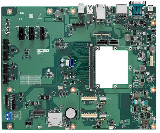
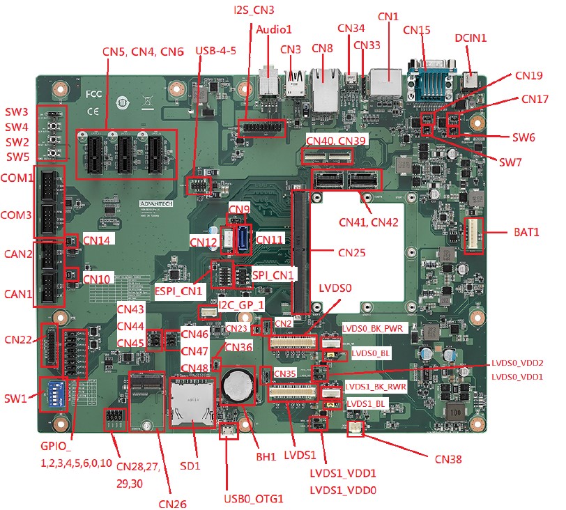
ROM-5721 接口布局圖 Board Dimension Layout
主板内置插针式引脚排序方式 (Pin Header defination)
Internal I/O
| Position | Description | Connector Type |
|---|---|---|
| BAT1 | PIN Header for Battery | WAFER 8P 2.54mm 180D(M) DIP A2543WV2-8P |
| BH1 | RTC Battery Holder | BATTERY HOLDER 24.923.48.9 CR2032 BH800.4GG |
| CAN1 | CANBus Port 1 | BOX HEADER 5x2P 2.54mm 180D(M) DIP 23N6960-10S10 |
| CAN2 | CANBus Port 2 | BOX HEADER 5x2P 2.54mm 180D(M) DIP 23N6960-10S10 |
| COM1 | COM Port 1 | BOX HEADER 5x2P 2.54mm 180D(M) DIP 23N6960-10S10 |
| COM3 | COM Port 3 (Debug Port) | BOX HEADER 5x2P 2.54mm 180D(M) DIP 23N6960-10S10 |
| CN4 | PCIex1 Connector 1 | PCIEXPRESS 36P 180D(F) DIP 2EG01817-D2D-DF |
| CN5 | PCIex1 Connector 2 | PCIEXPRESS 36P 180D(F) DIP 2EG01817-D2D-DF |
| CN6 | PCIex1 Connector 3 | PCIEXPRESS 36P 180D(F) DIP 2EG01817-D2D-DF |
| CN11 | SATA Connector | Serial ATA 7P 1.27mm 180D(M) DIP WATM-07DBN4A3B8 |
| CN12 | SATA Power Connector | WAFER 4P 2.5mm 180D(M) DIP 24W1161-04S10-01T |
| CN22 | GPIOx8 sets | PIN HEADER 10x2P 2.0mm 180D(M) DIP 21N22050 |
| CN25 | MXM 3.0 Connector | MXM Conn. 314P 90D(F) SMD AS0B821-S78B-7H |
| CN26 | M.2 Key E Slots | NGFF 75P 0.5mm 90D(F) H=4.2mm SMD AS0BC21-S40BE |
| CN38 | FAN (Reserved) | WTB Con. 3P 2.54mm 180D(M) DIP A2543WV0-3P-6T-5e |
| CN39 | MIPI-CSI1 (FPC, 4-Lane) | FPC 39P, 0.6mm, H0.9mm |
| CN40 | MIPI-CSI0 (FPC, 2-Lane) | FPC 39P, 0.6mm, H0.9mm |
| CN41 | MIPI-CSI0 (Mini-SAS, 2-Lane) | Mini SAS 36P/0.8mm/(M)/LCP/VA/G15u/S/BK/W |
| CN42 | MIPI-CSI1 (Mini-SAS, 4-Lane) | Mini SAS 36P/0.8mm/(M)/LCP/VA/G15u/S/BK/W |
| ESPI_CN1 | ESPI | PIN HEADER 6x2P 2.0mm 180D(M) SMD 21N22050-12M00B |
| I2C_GP_1 | I2C Pin Header | WAFER BOX 4P 2.00mm 180D(M) DIP 721-81-04TW00 |
| I2C_CN3 | Audio Codec Board | PIN HEADER 2x10P 2.54mm 180D(M) DIP 21N22564 |
| LVDS0 | LVDS0 | Wafer 2x20P/1.25mm/(M)/NY9T/VA/GFL/S/WH/W |
| LVDS_BK_PWR | LVDS0 Back Light | WAFER BOX 5P 2.0mm 180D(M) DIP A2001WV2-5P |
| LVDS1 | LVDS1 | Wafer 2x20P/1.25mm/(M)/NY9T/VA/GFL/S/WH/W |
| LVDS1_BK_PWR | LVDS1 Back Light | WAFER BOX 5P 2.0mm 180D(M) DIP A2001WV2-5P |
| SD1 | SD Card Slot | SD CARD 9P 90D(F) SMD WK2192CS3D-7H |
| SPI_CN1 | SPI Pin Header | PIN HEADER 4x2P 2.54mm 180D(M) SMD 21N22564 |
| SW2 | Reset Button | TACT SW STS-091 SMD 4P H=3.8mm |
| SW4 | SLP Button | TACT SW STS-091 SMD 4P H=3.8mm |
| SW5 | Power Button | TACT SW STS-091 SMD 4P H=3.8mm |
| USB0_OTG1 | USB OTG | Micro USB 5P/0.65mm/(F)/NY9T/GFL/RA/S/BK/B |
| USB-4-5 | USB Port 4, Port 5 | PIN HEADER 2x5P 2.0mm 180D(M) SMD 21N22050 |
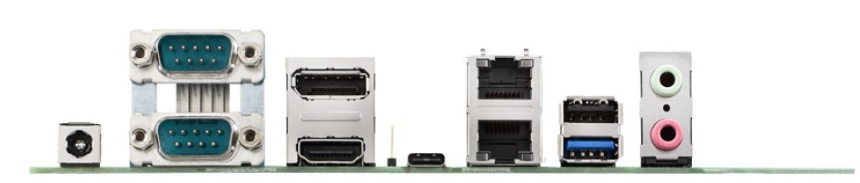
Rear I/O
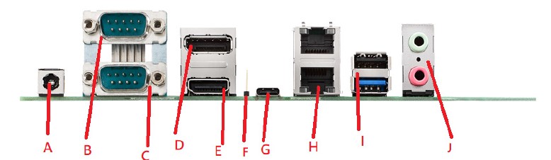
| Position | Description | Name |
|---|---|---|
| DCIN | DC Jack | A |
| CN15A | UART Port 0 | B |
| CN15B | UART Port 2 | C |
| CN1A | DP Port | D |
| CN1B | HDMI Port | E |
| CN33 | Type C Controller Programming Header (Reserved Only) | F |
| CN34 | USB Type C | G |
| CN8 | GbE Ethernet Connector Port | H |
| CN3 | USB Port 1/2 | I |
| Audio1 | MIC Input/Audio Output | J |
接口引脚定義 (Pin definitions)
- 電池(BAT1) & 電池扣(BH1)
- CAN(CAN1,CAN2)
- 串口(COM_DB(COM3)、COM1、UART0、UART2)
- 显示接口(LVDS、LVDS Backlight、HDMI、DP)
- LAN接口(LAN)
- USB接口(USB1-2、USB-4-5、USB Type C、USB OTG)
- 音频接口(Audio Output & Audio Codec)
- GPIO接口
- MINI_PCIE接口、M.2接口、SPI、I2C接口
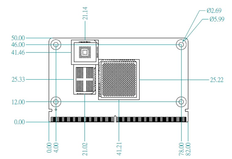
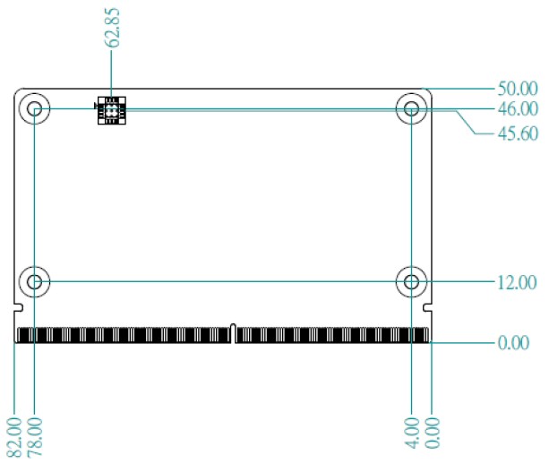
机械尺寸 (Mechanical Characteristics)
快速入门 (Quick Start)
系统下载 (OS Download)
- Linux系统 (Linux OS)
Yocto 2.5: IoTGateway/BSP/Linux/iMX8/OS Support List
Yocto 3.0: IoTGateway/BSP/Linux/iMX8/OS Support List 3.0
Linux 燒錄方法 (Linux Flash eMMC Method)
使用Flash tool 燒錄鏡像到eMMC (Flash image into eMMC by Flash Tools)
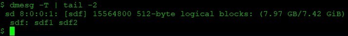
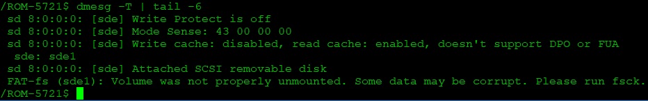
Step0: 檢查SD卡在Linux 環境的代號 (check SD card symbol in Linux system)
Step1: 創造一張可開機的SD 卡 (Create a bootable SD card)
![]()
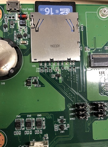
Step2: 將可開機的SD 卡插入底板SD卡卡槽 (Plug the SD card into Carrier board's SD card slot)
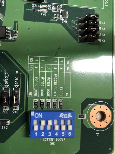
Step4: 確認開機選擇指撥開關 (Check the boot switch)
SD 卡開機模式 (SD boot mode):
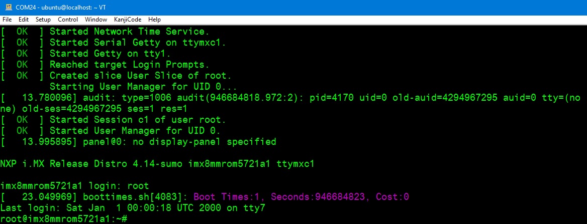
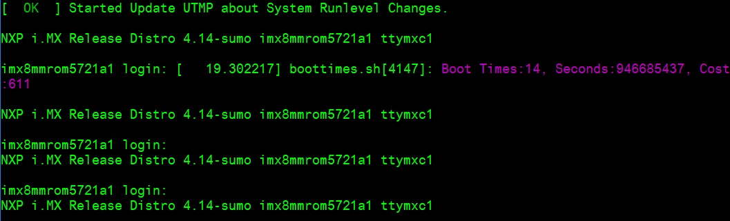
Step3: 打開電源 和 終端機 (Turn on the Power & Terminal)
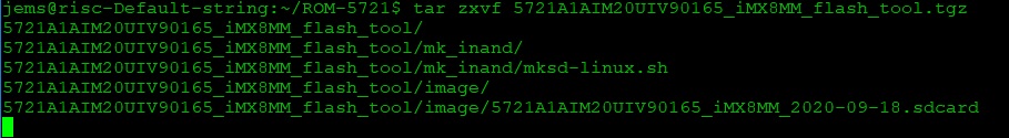
Step4: 解壓縮flash tools 檔案,並複製到U盤中 (Unzip the flash tools file, then copy to USB Disk)
解壓縮 (Unzip the file)
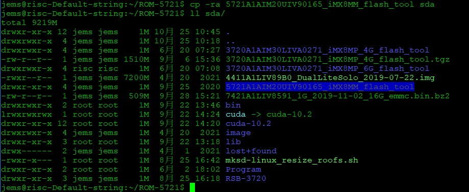
複製檔案到U盤中 (Copy the flash file to USB Disk)
-
插入U盤到你的Ubuntu 電腦上 (Plug the USB Disk into your Linux PC)
-
檢視U盤在Ubuntu 系統代號 (Check the USB Disk's symbol in Ubuntu System)
- 掛載U盤在Ubuntu 系統中 (Mount the USB Disk in Ubuntu System)
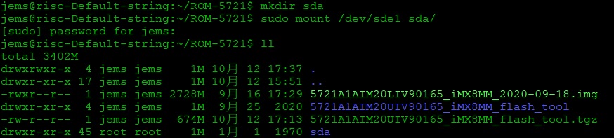
- 複製檔案到U盤 (Copy the file to USB disk)
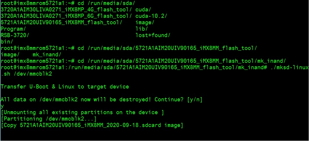
- 將U盤連接到ROM-5721系統, 進入flash tool下的mk_inand資料夾, 執行指令
./mksd-linux.sh /dev/mmcblk2燒錄image到eMMC
| ROM-5721 | |
|---|---|
| SD card | /dev/mmcblk1 |
| eMMC | /dev/mmcblk2 |
- 切換開機switch 1:on 2,3,4,5,6:off 來設定成從eMMC開機 (Change boot switch to "1:on 2,3,4,5,6:off" to boot from eMMC. Reboot system).
Debug 串口調試 (Debug port Setting)
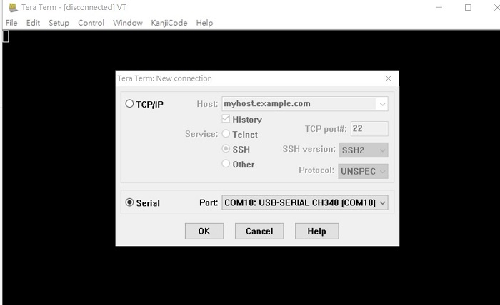
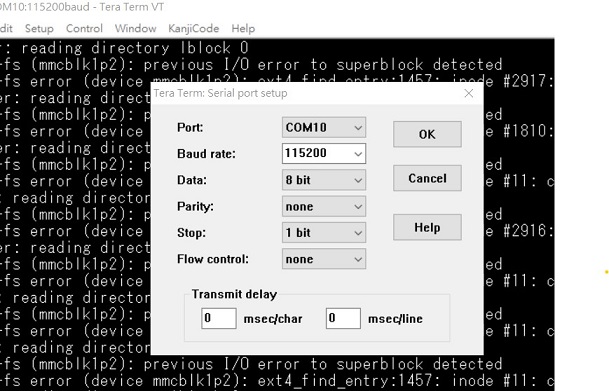
以 Tera Term 为例介绍如何使用串口调试功能
Baud Rate波特率:115200
Data 数据位:8
Parity 奇偶校验:无
Stop 停止位:1
Flow Control流控:无
Tera Term Tool
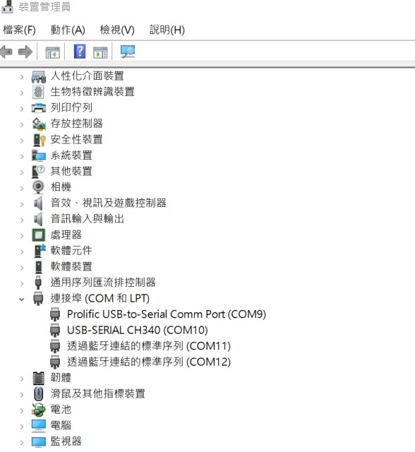
Check the Serial port in Device Manager (查看PC端的串口号):
if you can not identify the Serial device, please check your serial driver.
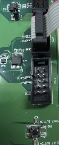
Debug port connection (串口連接)
Log into Terminal Tool (进入串口调试终端):
Linux系统的基本使用(Linux System Basic Operating Method)
UUU 使用方法(USB Connection (OTG port))
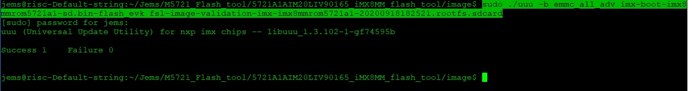
Download uuu tool from (ADV v20200619 · ADVANTECH-Corp/uuu · GitHub) or in the folder.
The "imx-boot-imx8mmrom5721a1-sd.bin-flash_evk" file be included in 5721A1AIM20LIV90XXX_iMX8MM_misc.tgz. XXX is the version.
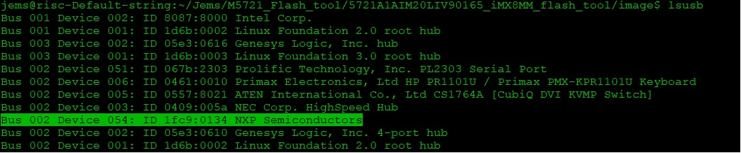
Connect USB cable to USB OTG port.
Change boot switch to "4:on 1,2,3,5,6:off" to boot from force recovery mode.
Type command below to flash eMMC:
Display Setting (ROM-5721)
U-boot Command:
setenv fdt_file xxxx.dtb
env save
boot
U-boot load default setting:
env default -a
env save
reset
- Display: Default support g070vw01 LVDS panel on LVDS0
Yocto 2.5
| Display | DTB File |
|---|---|
| DSI to LVDS g070vw01 | adv-imx8mm-rom5721-a1.dtb |
| DSI to LVDS g150xgel05 | adv-imx8mm-rom5721-a1-dsi2lvds-g150xgel05.dtb |
| DSI to LVDS g215hvn01 | adv-imx8mm-rom5721-a1-dsi2lvds-g215hvn01.dtb |
| DSI to DP | adv-imx8mm-rom5721-a1-dsi2dp.dtb |
| DSI to HDMI | adv-imx8mm-rom5721-a1-adv7535.dtb |
| DSI auog101uan02 | adv-imx8mm-rom5721-a1-auog101uan02.dtb |
| M.2 SDIO | adv-imx8mm-rom5721-a1-m2-sdio.dtb |
| M.2 I2S | adv-imx8mm-rom5721-a1-m2-i2s.dtb |
Yocto 3.0
| Display | DTB File |
|---|---|
| DSI to LVDS g070vw01 | imx8mm-rom5721-a1.dtb |
| DSI to LVDS g150xgel05 | imx8mm-rom5721-a1-dsi2lvds-g150xgel05.dtb |
| DSI to LVDS g215hvn01 | imx8mm-rom5721-a1-dsi2lvds-g215hvn01.dtb |
| DSI to DP | imx8mm-rom5721-a1-dsi2dp.dtb |
| DSI to HDMI | imx8mm-rom5721-a1-adv7535.dtb |
| DSI auog101uan02 | imx8mm-rom5721-a1-auog101uan02.dtb |
| M.2 SDIO | imx8mm-rom5721-a1-m2-sdio.dtb |
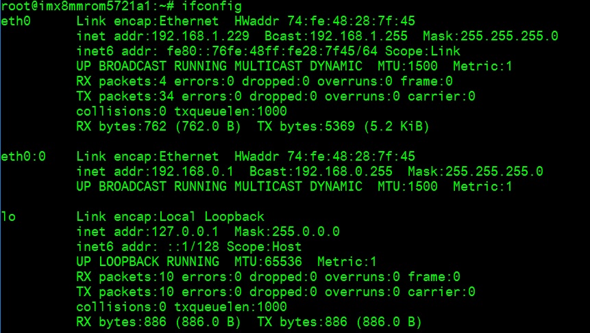
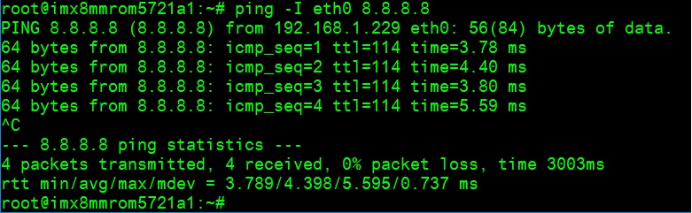
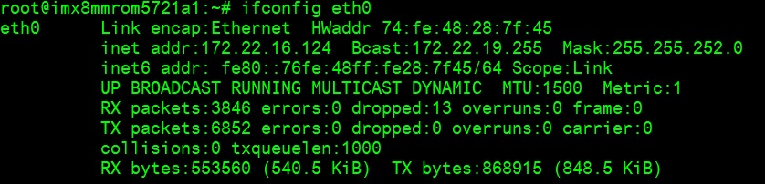
乙太網路使用方法(Ethernent Testing Method)
Command: ifconfig
Command: ping -I eth1 8.8.8.8 or ping -I eth0 8.8.8.8
WiFi使用方法(WIFI Testing Method)
# 安裝WIFI天線到ROM-5721上
ifconfig mlan0 up
iwlist mlan0 scan

# WPA2 連線
wpa_passphrase "SSID" 123456789 > /tmp/wpa.conf
wpa_supplicant -BDwext -imlan0 -c/tmp/wpa.conf
udhcpc -b -i mlan0
ifconfig
ping 8.8.8.8
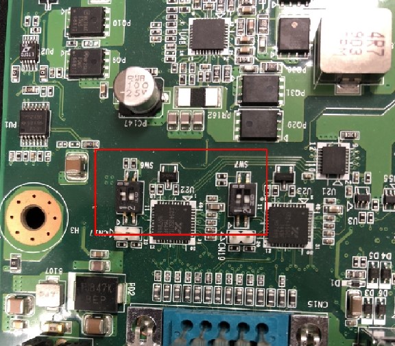
串口使用方法(Serial Port Operating Method)
RS-232 Test
- CN15上 (SER0/UART3):
/dev/ttymxc2 - CN15 下 (SER2/UART1):
/dev/ttymxc0 - COM 3 (A53 debug/SER3/UART2):
/dev/ttymxc1 - COM 1 (M4 debug/SER1/UART4):
/dev/ttymxc3
SW7 Setting (SW7設置)
MODE1  MODE0
  0      0    LOOPBACK
  0      1    RS232
  1      0    RS485
  1      1    RS422
Loopback test (eg. ttymxc0) — Connect loopback test tool:
stty -F /dev/ttymxc0 115200
stty -F /dev/ttymxc0 -echo
cat /dev/ttymxc0 &
echo test > /dev/ttymxc0
GPIO使用方法(GPIO Operating Method)
# Loop-back Test (Take GPIO0 and GPIO2 as examples)

# Step 1: Connect GPIO0 and GPIO2
# Step 2: Export GPIO interface
echo 496 > /sys/class/gpio/export
echo 497 > /sys/class/gpio/export

# Step 3: Set direction
echo out > /sys/class/gpio/gpio1/direction
echo in > /sys/class/gpio/gpio2/direction

# Step 4: Read value and set output value then check
cat /sys/class/gpio/gpio2/value
# 0
echo 1 > /sys/class/gpio/gpio1/value
cat /sys/class/gpio/gpio2/value
# 1
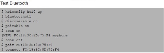
蓝牙使用方法(BlueTooth Operating Method)
$ hciconfig hci0 up
$ bluetoothctl
$ discoverable on
$ pairable on
$ scan on
[NEW] FC:18:3C:8D:75:F4 myphone
$ scan off
$ pair FC:18:3C:8D:75:F4
$ connect FC:18:3C:8D:75:F4
遠程訪問及文件傳輸(Remote Access and File Transimmion)
查看主板IP位址 (Check IP Address):
ifconfig
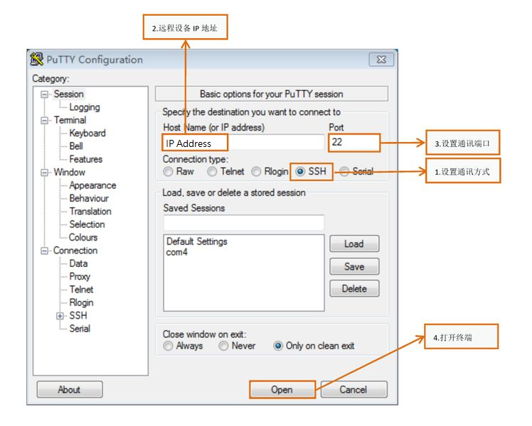
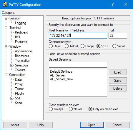
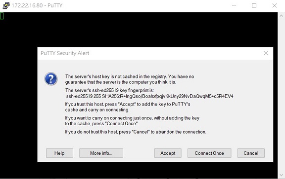
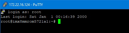
Windows下SSH访问及文件传输
SSH Remote Log into Device
- SSH远程登录,以putty选择putty.exe(或者使用Xshell、SecureCRT等类似软件)
- 需要设置远程设备的IP、通讯端口(默认22)、通讯方式,登录后验证用户名密码
通用方法(General Method)
查看CPU温度(Check CPU Temperature)
cat /sys/devices/virtual/thermal/thermal_zone0/temp
# 44600

# 或者直接以度爲單位顯示
echo $[$(cat /sys/class/thermal/thermal_zone0/temp)/1000]°
# >>> 45°
查看CPU频率(Check CPU Frequency)
cat /sys/devices/system/cpu/cpu0/cpufreq/cpuinfo_cur_freq
# >> 900000
cat /sys/devices/system/cpu/cpu0/cpufreq/cpuinfo_max_freq
# >> 1200000
查看内存容量(Check Memory Capacity)
busybox free -m
#              total       used       free     shared    buffers     cached
# Mem:       1794920     516080    1278840      17252      9852        80292
# -/+ buffers/cache:     425936    1368984
# Swap:            0          0          0
查看存储容量(Check Storage Capacity)
busybox df -h
網路Ping測試(Ping Network Testing)
ping 8.8.8.8
# PING 8.8.8.8 (8.8.8.8) 56(84) bytes of data.
# 64 bytes from 8.8.8.8: icmp_seq=1 ttl=54 time=2.10 ms
# 64 bytes from 8.8.8.8: icmp_seq=2 ttl=54 time=2.10 ms
設置RTC (RTC Setting)
systemctl stop ntpdate.service
date 090816072021 && hwclock -w && date
# Wed Sep  8 16:07:00 UTC 2021
# Wed Sep  8 16:07:00 UTC 2021
date
# Wed Sep  8 16:07:06 UTC 2021
Linux BSP編譯方法(Linux BSP Compile Method)
Yocto 4.2
Yocto 4.0
Yocto 3.0
Yocto 2.5
Build known issue
如果有驗證上的錯誤 請使用以下的方法
repo sync failed — Server certificate verification failed
export GIT_SSL_NO_VERIFY=1
# or
git config --global http.sslverify false
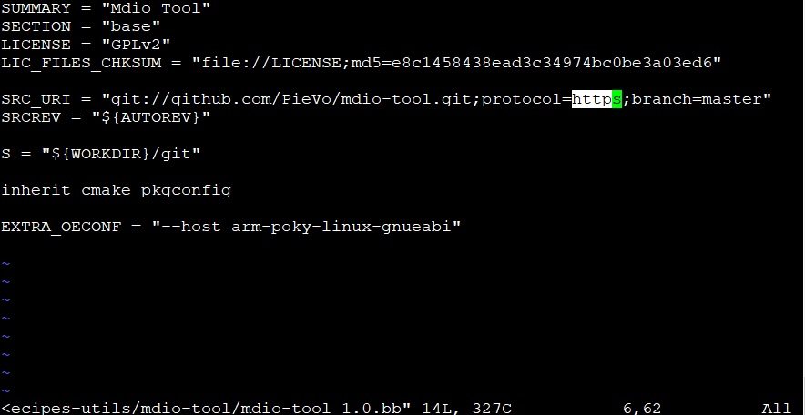
Build error with git protocol
ERROR: ExpansionError during parsing .../mdio-tool_1.0.bb
fatal: remote error: The unauthenticated git protocol on port 9418 is no longer supported.
Modify mdio-tool_1.0.bb:
SRC_URI = "git://github.com/PieVo/mdio-tool.git;protocol=https;branch=master"
nnshark error
https://community.nxp.com/t5/i-MX-Processors/Yocto-3-3-5-10-72-BSP-Build-Fail/m-p/1487902