RSB-3720 user guide
Contents
- 1. 產品介紹 (Product Introduction)
- 2. 硬件接口說明 (Hardware Interface Introduction)
- 3. 快速入門 (Quick Start)
- 4. Linux 系統的基本使用 (Linux System Basic Operating Method)
- 4.1 Display Setting (RSB-3720)
- 4.2 乙太網路使用方法 (Ethernet Testing Method)
- 4.3 WiFi 使用方法 (WiFi Testing Method)
- 4.4 4G 使用方法 (4G Testing Method)
- 4.5 GPIO 使用方法 (GPIO Operating Method)
- 4.6 LED_USER 使用方法
- 4.7 COM1 複合使用方法 (COM1 Complex Port Operating Method)
- 4.8 CANBus or CAN-FD
- 4.9 藍牙使用方法 (Bluetooth Operating Method)
- 4.10 音訊使用方法 (Audio Operating Method)
- 4.11 I2C 測試 (I2C Test Method)
- 4.12 看門狗測試 (Watch Dog Test Method)
- 4.13 攝像頭測試 (Camera Test Method)
- 4.14 遠程訪問及文件傳輸 (Remote Access and File Transmission)
- 5. 通用方法 (General Method)
- 6. Build Known Issue
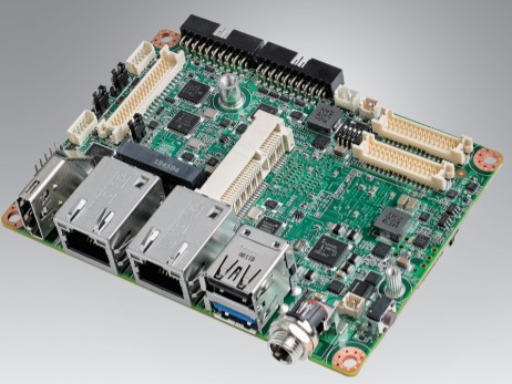
產品介紹(Product introduction)
產品特性(Product Features)
- NXP Arm® Cortex®-A53 i.MX8M Plus Quad/Dual up to 1.8 GHz
- Onboard LPDDR4 4 GB / 6 GB, 4000MT/s memory
- HDMI 1920x1080 at 60Hz, 1 Single or 1 Dual Channel 24 bit LVDS (or 1 4-Lane MIPI-DSI by BOM Option)
- 1 4-wire RS-232/422/485, 1 USB3.2 Gen1 By 1, 1 USB2.0, 1 Micro SD, 1 Mic. in / Line out
- 1 mini-PCIe for 3G/4G, 1 M.2 2230 Key E Slot
- Supports Yocto Linux and Android
- Support I/O Expansions boards by UIO40-Express
產品官網連結(Product official website link)
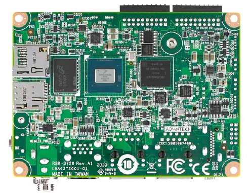
硬件接口說明(Hardware interface introduction)
接口布局和尺寸(Layout and Sizes)
RSB-3720 接口布局圖(Board Dimension Layout)
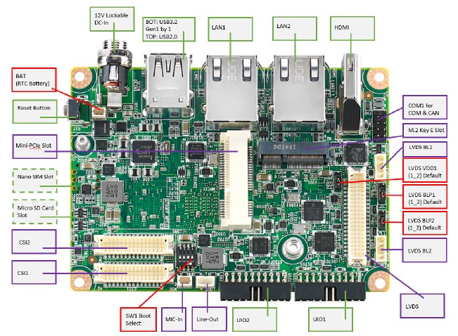
| BAT | RTC Battery Connector |
|---|---|
| BL1 | LVDS Backlight 1 |
| BL2 | LVDS Backlight 2 |
| COM1 | COM + CAN Pin Header (default as debug console) |
| CSI1 | MIPI-CSI Camera Input 1 |
| CSI2 | MIPI-CSI Camera Input 2 |
| DCIN/DCIN 1 | 12V DC Power Input by DC Jack / by Pin Header |
| HDMI | HDMI CONN |
| LAN1 | Ethernet 1 |
| LAN2 | Ethernet 2 |
| LOUT | Line Out Pin Header |
| LVDS | LVDS CONN. |
| M2 | M.2 Key E CONN. |
| MIC | MIC In Pin Header |
| MPCIE | Mini-PCIe CONN. |
| RST | Reset Button |
| SD | SD Slot |
| UIO1 | UIO40-Express Pin Header 1 |
| UIO2 | UIO40-Express Pin Header 2 |
| USB1 | USB CONN. (USB 3.2 Gen 1 on TOP + USB 2.0 on BOT) |
接口引脚定義 (Pin definitions)
- BLP1
- BLP2
- BAT (RTC Battery CONN.)
- BL1 (LVDS Backlight 1)
- BL2 (LVDS Backlight 2)
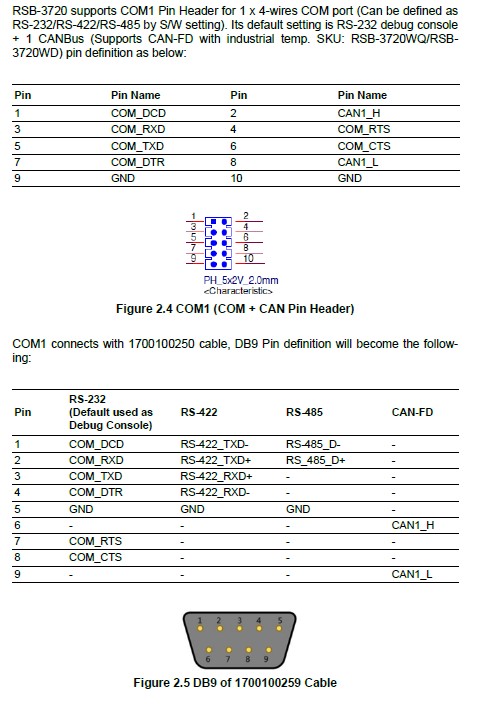
- COM1 (COM + CAN Pin Header)
- CSI1 (MIPI-CSI Camera Input 1)
- CSI2 (MIPI-CSI Camera Input 2)
- DCIN/DCIN1 (12V DC Power Input)
- HDMI (HDMI CONN.)
- LAN1 (Ethernet eth0)
- LAN2 (Ethernet eth1)
- LOUT (Line Out Pin Header)
- LVDS (LVDS CONN.)
- M2 (M.2 Key E CONN.)
- MIC (MIC In Pin Header)
- MPCIE (Mini-PCIe CONN.)
- RST (Reset Button)
- SD (SD Slot)
- SIM (SIM Slot)
- UIO1 (UIO40-Express Pin Header 1)
- UIO2 (UIO40-Express Pin Header 2)
- USB 1 (USB 3.2 Gen 1 on TOP + USB 2.0 on BOT)
- LED
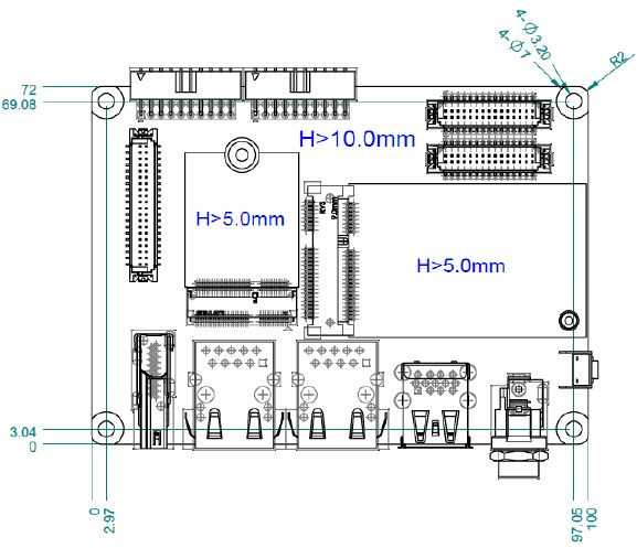
機械尺寸 (Mechanical Characteristics)
快速入門 (Quick Start)
系统下载 (OS Download)
- Linux系统 (Linux OS)
Download mksd-linux.sh:
https://github.com/ADVANTECH-Corp/RISC_tools_scripts/blob/kirkstone/imx8/mksd-linux.sh
Download "Product_AIM_Release_version"_flash_tool.tgz, unzip it, copy mksd-linux.sh to mk_inand folder, then run mksd-linux.sh.
Linux 燒錄方法 (Linux Flash eMMC Method)
1. 創建一個可以開機的SD Card (Create a bootable SD card)
先確認SD卡在Ubuntu 系統(x86) 所認到的SD卡代號 (Check the SD card symbol in Ubuntu System (x86))
Command: sudo fdisk -l

2. 燒錄鏡像到SD 卡中 (Flash Image into SD card)
sudo dd if=3720A1AIM30LIVA0333_iMX8MP_6G_2021-10-05.img of=/dev/sdf bs=1M conv=fsync

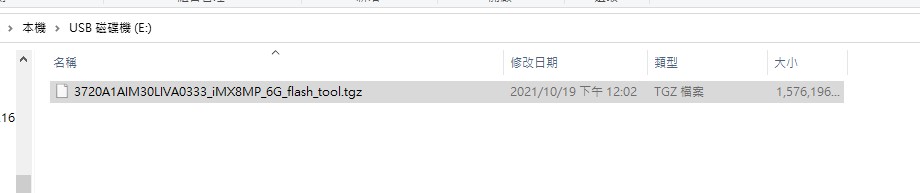
3. 將flash tool 拷貝到U盤 (Copy the eMMC flash tool into USB Disk)
4. 設定終端機 (Set Debug Terminal)
以 Tera Term 為例介绍如何使用串口調試功能
波特率(Baud Rate):115200
數據位(Data):8
奇偶校驗(Parity):无 (none)
停止位(Stop):1
流控(Flow Control):无 (none)
Check the Serial port in Device Manager (查看PC端的串口號). If you cannot identify the Serial device, please check your serial driver.
5. 將可開機的SD 卡插入 SD 插槽, 並打開電源開機 (Plug the SD card into SD Card Slot, then turn on the power)
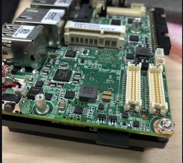
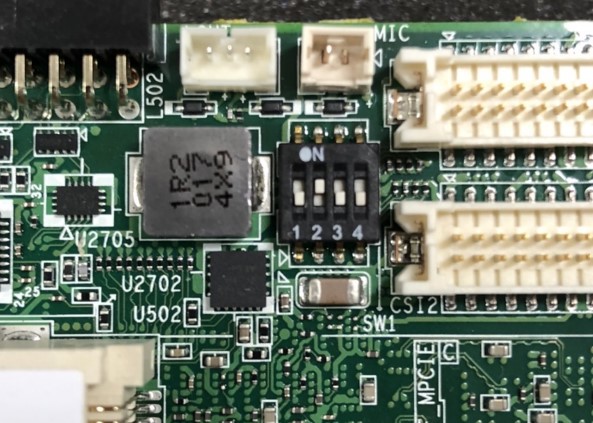
6. 確認撥碼開關 為 SD 卡開機模式 (Check the Switch)
SD 卡開機: 1, 2 on (Set the SD card boot up mode: 1 on, 2 on)
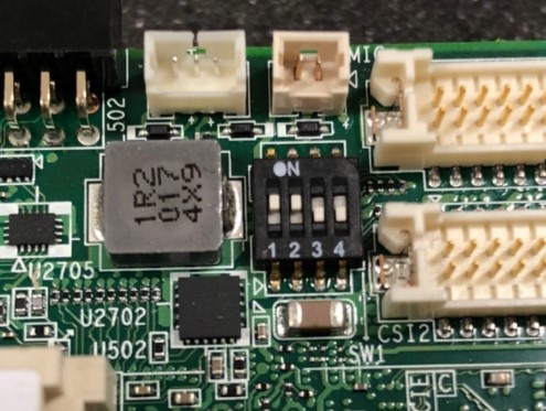
eMMC 開機: 2 on (Set the eMMC boot up mode: 2 on, others off)
7. 打開電源,由終端機可看到開機訊息 (Turn on the power, you will see the debug message from Terminal tool)
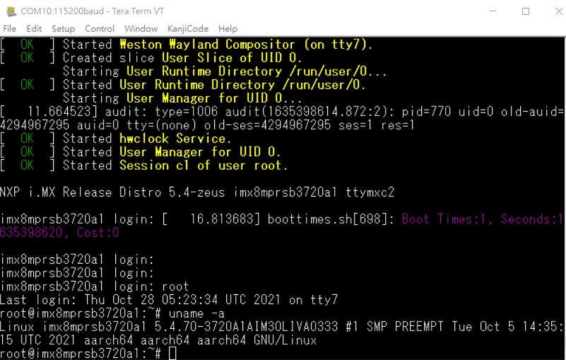
8. 開機後請再重新開機一次,系統將會重新劃分磁區大小。(Reboot once; the system will reconfigure the partition.)
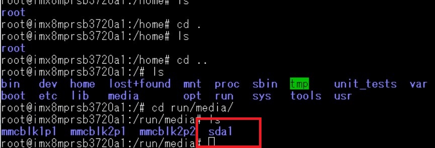
9. 燒錄eMMC前, 請將U盤插入USB port (Plug the USB Disk into USB port before flashing eMMC)
10. 在系統確認U盤 (Check the USB disk in the Yocto System)
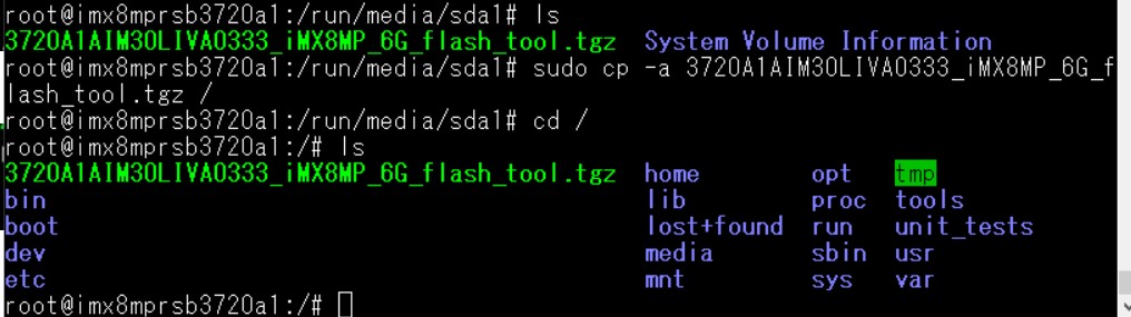
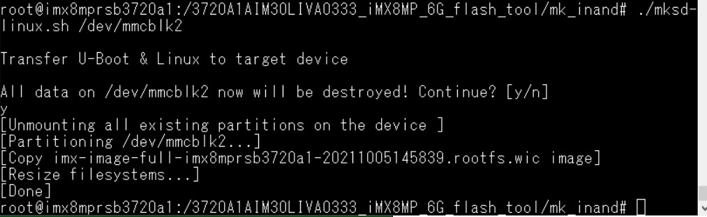
11. 將flash tool 燒錄鏡像,拷貝到根目錄 (Copy the flash tool into root file system)

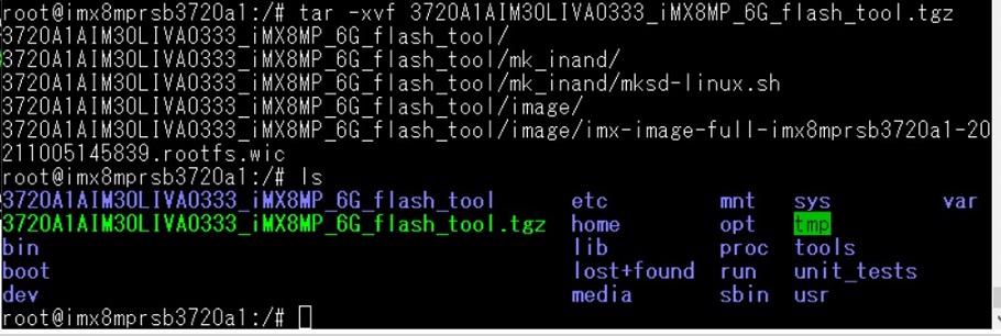
12. 解壓縮 flash tool (Unzip the flash tool)
13. 執行燒錄eMMC (Execute the eMMC flash script)
Note: eMMC: /dev/mmcblk2
14. 移除SD卡, 重新開機, 並切換撥碼開關 (Remove the SD card, change the switch to eMMC mode, then reboot)
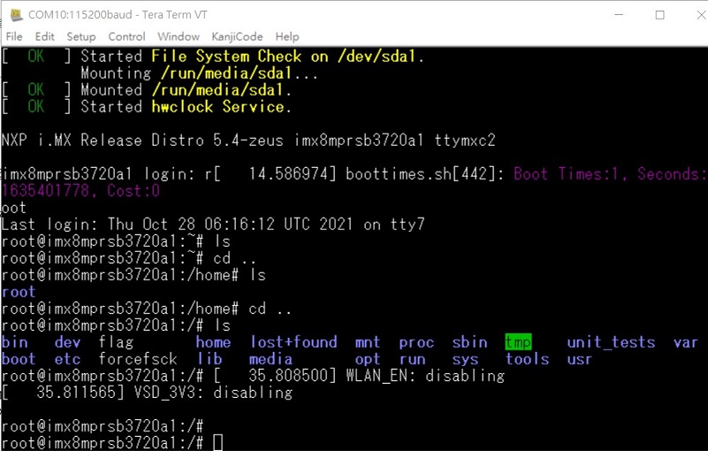
15. 從eMMC 開機, debug 訊息 (You will see the debug message when booting from eMMC)
Linux系统的基本使用(Linux System Basic Operating Method)
Display Setting (RSB-3720)
U-Boot Command
setenv fdtfile <dtb_filename>
saveenv
reset
Display
| Display Configuration | DTB File |
|---|---|
| HDMI (default) | imx8mp-rsb3720-a1.dtb |
| LVDS0 (g070vw01) + HDMI | imx8mp-rsb3720-a1-lvds0-auo.dtb |
| LVDS1 (g070vw01) + HDMI | imx8mp-rsb3720-a1-lvds1-auo.dtb |
| Dual LVDS (g215hvn01) + HDMI | imx8mp-rsb3720-a1-lvds-dual.dtb |
| DSI → HDMI (adv7535) + HDMI | imx8mp-rsb3720-a1-adv7535.dtb |
| DSI (auog101uan02) + HDMI | imx8mp-rsb3720-a1-auog101uan02.dtb |
Camera
| Camera Configuration | DTB File |
|---|---|
| OV5640 (default) | imx8mp-rsb3720-a1.dtb |
| Basler Camera | imx8mp-rsb3720-a1-basler.dtb |
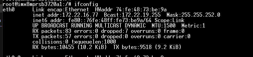
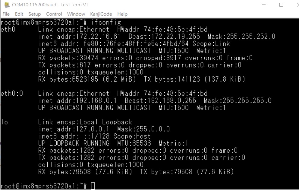
乙太網路使用方法(Ethernent Testing Method)
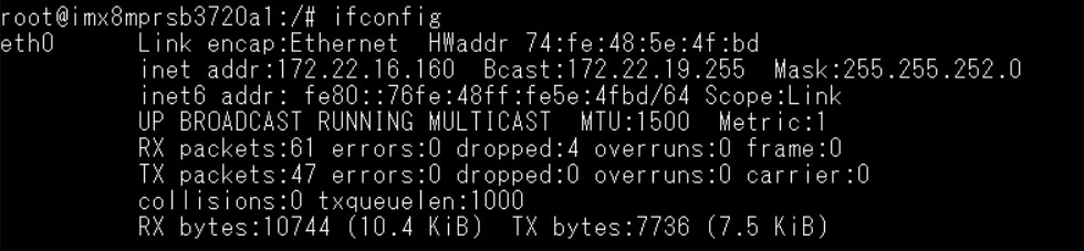
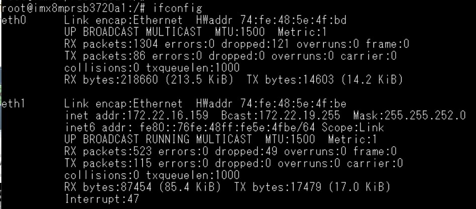
Command: ifconfig
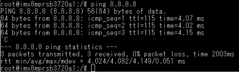
Command: ping 8.8.8.8
Change IP Addr Command — Check Active Ethernet interface:
root@imx8mprsb3720a1:~# connmanctl services
*AR Wired                ethernet_74fe485e4fbd_cable
Set static IP Addr:
connmanctl config <service> --ipv4 manual <ip address> <netmask> <gateway>
connmanctl config <service> --nameservers <dns-addr>
Example:
connmanctl config ethernet_74fe485e4fbd_cable --ipv4 manual 192.168.1.100 255.255.255.0 192.168.1.254
connmanctl config ethernet_74fe485e4fbd_cable --nameservers 8.8.8.8 4.4.4.4
RJ45 LED Indicator:
| Speed | Left | Right | Command |
|---|---|---|---|
| 10M | OFF | link green | ethtool -s eth0 autoneg on speed 10 duplex full |
| 100M | ON 橙 | link green | ethtool -s eth0 autoneg on speed 100 duplex full |
| 1000M | ON 綠 | link green | ethtool -s eth0 autoneg on speed 1000 duplex full |
WiFi使用方法(WIFI Testing Method)
# killall wpa_supplicant
# ifconfig wlan0 up
# wpa_passphrase "SSID" "PASSWORD" > /tmp/wpa.conf
# wpa_supplicant -BDwext -iwlan0 -c/tmp/wpa.conf
# udhcpc -b -i wlan0
# ifconfig
# ping 8.8.8.8
4G使用方法(4G Testing Method, Test with EWM-C117)
Check and change module to pppd mode:
# stty -F /dev/ttyUSB3 -echo
# cat /dev/ttyUSB3 &
# echo AT+UUSBCONF? > /dev/ttyUSB3

Change to pppd mode:
# echo AT+UUSBCONF=0 > /dev/ttyUSB3

# echo AT+CFUN=16 > /dev/ttyUSB3
![]()
The module will change to ttyACM0*, check again:
# stty -F /dev/ttyACM0 -echo
# cat /dev/ttyACM0 &
# echo AT+UUSBCONF? > /dev/ttyACM0

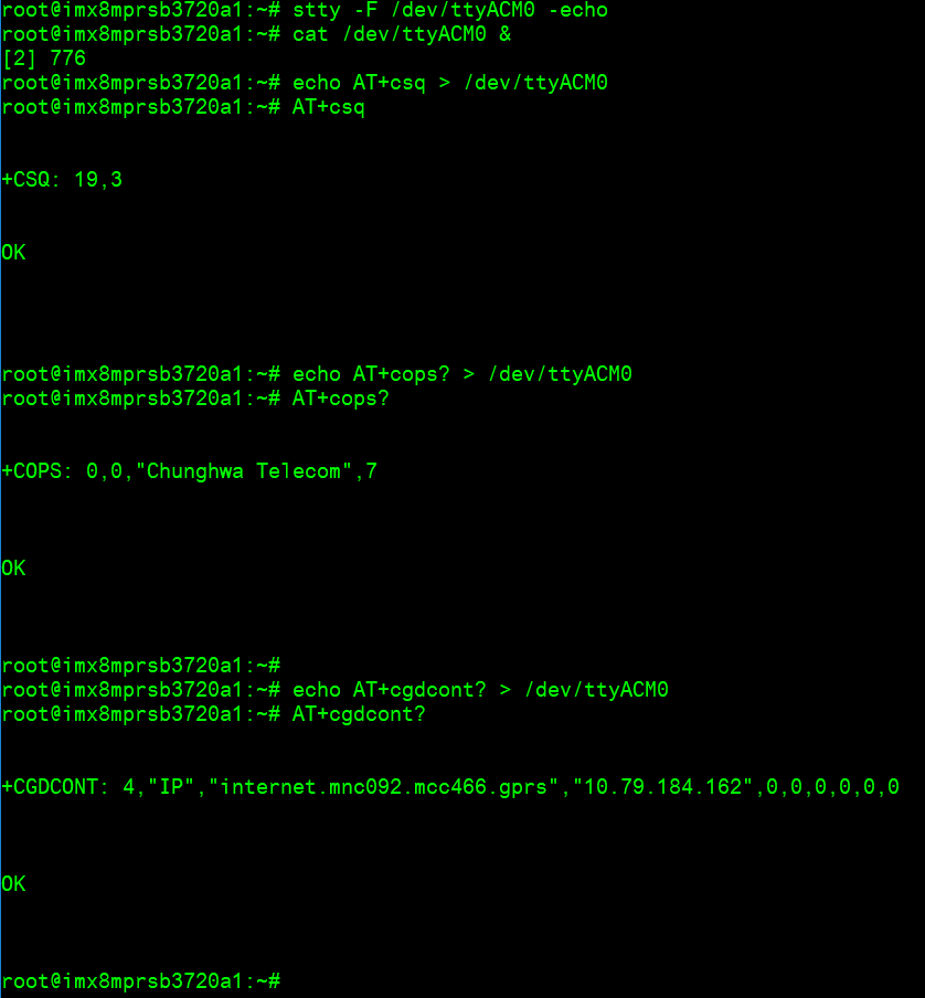
Set module to connect:
# stty -F /dev/ttyACM0 -echo
# cat /dev/ttyACM0 &
# echo AT+csq > /dev/ttyACM0
# echo AT+cops? > /dev/ttyACM0
# echo AT+cgdcont? > /dev/ttyACM0
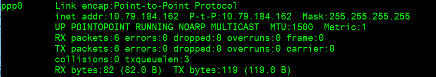
Connect to Internet:
# pppd connect 'chat -v -s -t 10 "" "AT" "" "ATDT*99***4#" "CONNECT" ""' \
  user username password password /dev/ttyACM2 460800 nodetach crtscts debug usepeerdns defaultroute &
# ifconfig
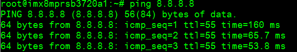
# ping 8.8.8.8
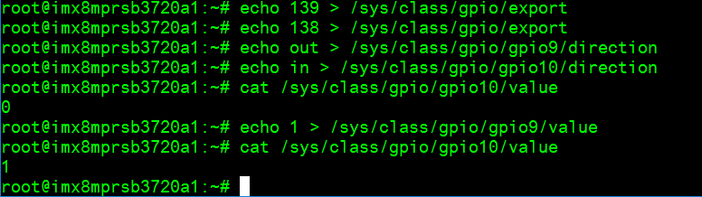
GPIO使用方法(GPIO Operating Method)
You can use the following command to check the GPIO usage information:
cat /sys/kernel/debug/gpio
Here is an example on RSB-3720 2G Yocto5.0:
GPIO output from the GPIO expander:
- gpiochip5: GPIOs 512-519, parent: i2c/0-0071, 0-0071
- gpiochip6: GPIOs 520-527, parent: i2c/0-0070, 0-0070
GPIO2 and GPIO4 — outputs from GPIO expander 0x70, mapped to 520–527 (P0–P7)
GPIO5 to GPIO10 — outputs from GPIO expander 0x71, mapped to 512–519 (P0–P7)
CPU GPIO number formula: ((bank-1) × 32) + gpio_pin
- GPIO11: ECSPI2_MOSI → GPIO5_IO11 → 139
- GPIO12: ECSPI2_SCLK → GPIO5_IO10 → 138
| RSB-3720 GPIO Pin | Source | Number (Yocto3.0/3.3/4.0/4.2) | Number (Yocto5.0) | Number (Yocto5.0 imx8LBVF0153+) | UIO-4030 GPIO |
|---|---|---|---|---|---|
| GPIO2 | i2c/0-0070, TCA9538 P5 | 501 | 525 | 517 | |
| GPIO4 | i2c/0-0070, TCA9538 P7 | 503 | 527 | 519 | |
| GPIO5 | i2c/0-0071, TCA9538 P0 | 504 | 512 | 520 | DB9-1 DI1# |
| GPIO6 | i2c/0-0071, TCA9538 P1 | 505 | 513 | 521 | DB9-6 DO1# |
| GPIO7 | i2c/0-0071, TCA9538 P2 | 506 | 514 | 522 | DB9-2 DI2# |
| GPIO8 | i2c/0-0071, TCA9538 P3 | 507 | 515 | 523 | DB9-7 DO2# |
| GPIO9 | i2c/0-0071, TCA9538 P4 | 508 | 516 | 524 | DB9-3 DI3# |
| GPIO10 | i2c/0-0071, TCA9538 P5 | 509 | 517 | 525 | DB9-8 DO3# |
| GPIO11 | MX8MP_IOMUXC_ECSPI2_MOSI__GPIO5_IO11 | 139 | 139 | 139 | DB9-4 DI4# |
| GPIO12 | MX8MP_IOMUXC_ECSPI2_SCLK__GPIO5_IO10 | 138 | 138 | 138 | DB9-9 DO4# |
Short GPIO pin 2 & pin 4
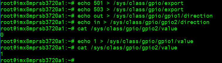
Short GPIO pin 5 & pin 6
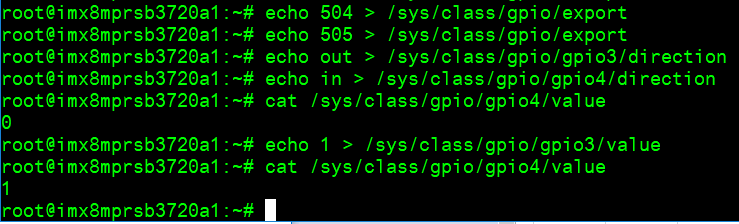
Short GPIO pin 7 & pin 8
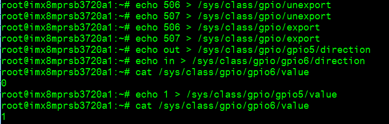
Short GPIO pin 9 & pin 10
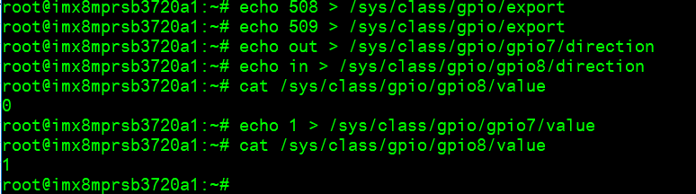
Short GPIO pin 11 & pin 12
LED_USER使用方法(LED_USER ON/OFF test)
ON:  echo 255 > /sys/class/leds/user/brightness
OFF: echo 0   > /sys/class/leds/user/brightness
COM1複合使用方法(COM1 complex Port Operating Method)
Note: please set the RS-485/RS-422 GPIO setting with SSH console.


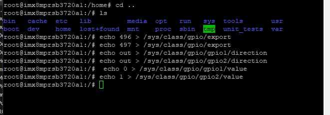
Set GPIO#496, #497:
Set to 0,1 for RS-485
Set to 1,1 for RS-422
Set to 0,0 for loopback
Set to 1,0 for RS-232
RS-232 (default as debug console)
# RS-485 test with Adam-4520
# Data- : Pin 1: COM_DCD
# Data+ : Pin 3: COM_RXD

# echo 496 > /sys/class/gpio/export
# echo 497 > /sys/class/gpio/export
# echo out > /sys/class/gpio/gpio1/direction
# echo out > /sys/class/gpio/gpio2/direction
# echo 0 > /sys/class/gpio/gpio1/value
# echo 1 > /sys/class/gpio/gpio2/value
# ./enable485 /dev/ttymxc2
# stty -F /dev/ttymxc2 speed 115200 ignbrk -brkint -icrnl -imaxbel -opost -onlcr -isig -icanon -iexten -echo -echoe -echok -echoctl -echoke
# cat /dev/ttymxc2 &
# echo "Serial Test" > /dev/ttymxc2
RS-232 — Disable console
Disable kernel message:
setenv mmcargs setenv bootargs ${jh_clk} console=${console} root=${mmcroot} video=HDMI-A-1:${videores} quiet
env save
reset
Disable debug port (Yocto machine setting):
# modify .../conf/machine/${MC}.conf
SERIAL_CONSOLES = ";"
Or via U-Boot:
setenv console disabled
env save
reset
CANBus or CAN-FD
(Note: RSB-3720CQ & RSB-3720CD → CANBus only; RSB-3720WQ & RSB-3720WD → CAN-FD only)
Step 1: Connect UIO-4034 A101-2 CANbus port Pin 2 and Pin 7 to RSB-3720 COM1 with 1700100250 cable.
Step 2: Set CAN0 and CAN1 up:
ip link set can0 up type can bitrate 125000
ifconfig can0 up
ip link set can1 up type can bitrate 125000
ifconfig can1 up
Step 3: candump CAN0:
candump can0 &
Step 4: Send from CAN1:
cansend can1 1F334455#1122334455667788
# can0  1F334455  [8]  11 22 33 44 55 66 77 88
藍牙使用方法(BlueTooth Operating Method)
# hciattach /dev/ttymxc0 bcm43xx 115200 flow
# hciconfig hci0 up
# hcitool scan
# bluetoothctl
# discoverable on
# pairable on
# scan on
# scan off
# pair 84:C5:A6:D3:AF:E4
# connect 84:C5:A6:D3:AF:E4
# info 84:C5:A6:D3:AF:E4
音訊使用方法(Audio Operating Method)
Line-in, Line-out, MIC
1. Line-out
gplay-1.0
2. MIC
arecord
Check audio codec:
# cat /proc/asound/cards
0 [sgtl5000   ]: sgtl5000 - sgtl5000
1 [audiohdmi  ]: audio-hdmi - audio-hdmi
Set Mic/audio volume:
amixer set Mic 100%
amixer set Lineout 100%
amixer set PCM 100%
Record and playback:
arecord -t wav -c 1 -r 44100 -d 5 /tmp/mic.wav
aplay /tmp/mic.wav
Record from MIC:
arecord -D plughw:0,0 -r 16000 -f S16_LE ./f-16000.wav
aplay f-16000.wav
Play wav file from codec:
aplay -D plughw:0,0 file_example_WAV_10MG.wav
Play wav file from HDMI:
aplay -D plughw:1,0 file_example_WAV_10MG.wav
Play wav file from HDMI with gst-launch:
gst-launch-1.0 filesrc location=LRMonoPhase4.wav ! wavparse ! audioconvert ! audioresample ! autoaudiosink
I2C 測試 (I2C Test method)
# Check I2C device (Audio codec: 0-000a)
i2cdetect -y 0

# I2C set and get
i2cset -f -y 0 0x0a 0 0xff00 w
i2cget -f -y 0 0x0a 0 w
# 0x11a0
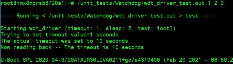
看門狗測試 (Watch Dog Test method)
# System will reboot after 1 sec
/unit_tests/Watchdog/wdt_driver_test.out 1 2 0
攝像頭測試 (Camera Test method)
# MIPI CSI0 - ov5640 Preview
gst-launch-1.0 v4l2src device=/dev/video0 ! video/x-raw,width=640,height=480 ! waylandsink

# MIPI CSI0 - ov5640 Capture
gst-launch-1.0 v4l2src num-buffers=1 device=/dev/video0 ! video/x-raw,width=640,height=480 ! jpegenc ! filesink location=sample.jpeg

# MIPI CSI1 - ov5640 Preview
gst-launch-1.0 v4l2src device=/dev/video1 ! video/x-raw,width=640,height=480 ! waylandsink

# MIPI CSI1 - ov5640 Capture
gst-launch-1.0 v4l2src num-buffers=1 device=/dev/video1 ! video/x-raw,width=640,height=480 ! jpegenc ! filesink location=sample.jpeg
遠程訪問及文件傳輸 (Remote Access and File Transmission)
查看主板IP位址 (Check IP Address):
ifconfig
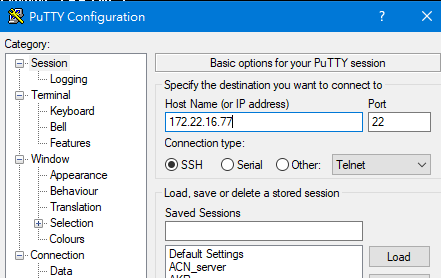
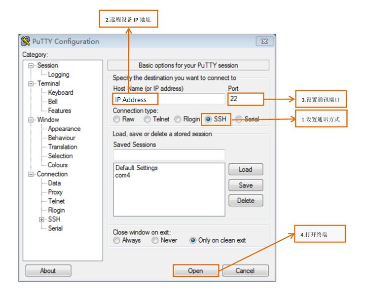
Windows下SSH訪問及文件傳輸
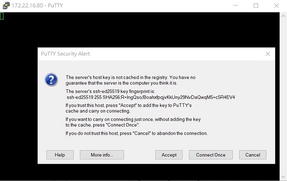
SSH Remote Log into Device
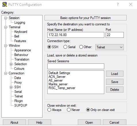
- SSH遠程登陸,以putty選擇putty.exe(或者使用Xshell、SecureCRT等類似軟件)
- 需要設置遠程設備的IP、通訊端口(默認22)、通訊方式,登錄后驗證用戶名密碼

通用方法(General Method)
查看CPU温度(Check CPU Temperature)
cat /sys/devices/virtual/thermal/thermal_zone0/temp
# 40000

# 或者直接以度爲單位顯示
echo $[$(cat /sys/class/thermal/thermal_zone0/temp)/1000]°
# >>> 40°
查看CPU频率(Check CPU Frequency)
cat /sys/devices/system/cpu/cpu0/cpufreq/cpuinfo_cur_freq
# >> 1200000
cat /sys/devices/system/cpu/cpu0/cpufreq/cpuinfo_max_freq
# >> 1800000
查看内存容量(Check Memory Capacity)
busybox free -m
#               total        used        free      shared  buff/cache   available
# Mem:        6002524      393988     5517304       18460       91232     5507676
# Swap:             0           0           0
查看存储容量(Check Storage Capacity)
busybox df -h
網路Ping測試(Ping Network Testing)
ping 8.8.8.8
設置固定IP與DNS(Set static IP address and DNS)
# cat /etc/systemd/network/20-wired.network
[Match]
Name=eth0
[Network]
DHCP=ipv4
DNS=8.8.8.8

# systemctl restart systemd-networkd
use connmanctl — Set static IP:
connmanctl config ethernet_74fe4873be98_cable --ipv4 manual 192.168.0.1 255.255.255.0 192.168.0.254
connmanctl config ethernet_74fe4873be98_cable --nameservers 8.8.8.8 8.8.4.4
Disable connman:
systemctl stop connman
systemctl disable connman
systemctl daemon-reload
systemctl restart systemd-networkd
設置RTC (RTC Setting)
Disable RTC sync service:
systemctl disable ntpd.service
![]()
systemctl stop systemd-timesyncd
systemctl stop ntpdate.service
![]()
Set system time, then write to RTC:
date 040710522021 && hwclock -w && date

Set incorrect time, then read time from RTC:
date 010100002000 && hwclock -r && date

Restart the RTC time to system time:
hwclock -s && date
![]()
設置LVDS clock (LVDS clock setting)
Reference:
Screenshot on Weston by weston-screenshooter
Add --debug in /lib/systemd/system/weston@.service:
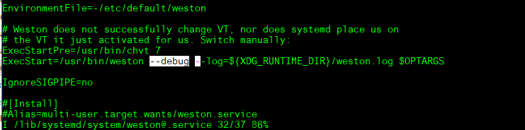
Reload the service:
systemctl daemon-reload
systemctl restart weston@root
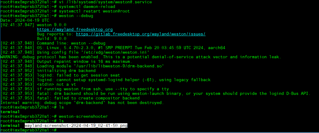
weston --debug
weston-screenshooter
It will generate wayland-screenshot*.png:
Autoexec program after login to the system
Place the script file under /etc/profile.d/:
cat /etc/profile.d/test.sh
# #!/bin/sh
# echo "I am running here..."
Others
Build known issue
如果有驗證上的錯誤 請使用以下的方法 (if you have the build error, please use git config --global http.sslverify false)
export GIT_SSL_NO_VERIFY=1
# or
git config --global http.sslverify false
Add git and vim into image — add in conf/local.conf:
IMAGE_INSTALL_append = " git-perltools vim "
Yocto 4.0 / 4.2 cannot fetch git submodule (nnshark):
At path "~/adv-release-bsp/$build_folder/tmp/work/armv8a-poky-linux/nnshark/2021.10.imx-r0/git"
git config submodule.common.url https://github.com/GStreamer/common.git
git submodule update
Fix in nnshark_2021.10.imx.bb:
-NNSHARK_SRC ?= "gitsm://github.com/nxp-imx/nnshark.git;protocol=https"
+NNSHARK_SRC ?= "git://github.com/nxp-imx/nnshark.git;protocol=https"
Reference: https://community.nxp.com/t5/i-MX-Processors/Yocto-3-3-5-10-72-BSP-Build-Fail/m-p/1487902
Yocto 5.0 devtool build u-boot-imx error:
cp: cannot stat '.../imx8mp_rsb3720a2_2G_defconfig/.config': No such file or directory
ERROR: Task (u-boot-imx_2024.04.bb:do_configure) failed with exit code '1'
Fix: uboot-config: Fix devtool modify
Ubuntu 24.04 build error — PermissionError: [Errno 1] Operation not permitted:
sudo apparmor_parser -R /etc/apparmor.d/unprivileged_userns
This temporarily removes the AppArmor restriction on unprivileged user namespaces, which Ubuntu 24.04 enforces by default. Reference: NXP Community