產品介紹
產品特性(Features)
NXP i.MX95 Cortex®-A55 AOM-5521 AI-on-Module Nano
- NXP Arm® Cortex®-A55 i.MX95 Six Cores up to 2.0 GHz
- 1 x Arm Cortex-M7 core & 1 x Cortex-M33 core
- Onboard LPDDR5 8 GB, 6400MT/s memory
- 1 x 4 lane MIPI-DSI (Optional), 1 x Dual channel LVDS, 1 x HDMI
- 1 x USB3.2 Gen1By1, 4 x USB2.0, 1 x USB 2.0 OTG, 4 x UART,
- 5 x I2C, 14 x GPIO, 1 x PCIe3.0, 1x10GbE +2x Gb Ethernet (w/TSN), 2 x CAN-FD
- Neural network accelerator built-in
產品官網連結(Product information Link)
接口布局和尺寸(Layout and Sizes)
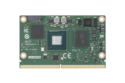
AOM-5521 接口布局圖 Board Dimension Layout
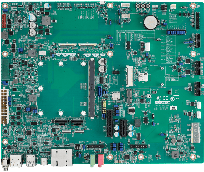
SOM-DB2510 接口布局圖 Board Dimension Layout
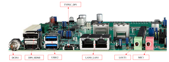
主板内置插针式引脚排序方式 (Pin Header defination)
Internal I/O
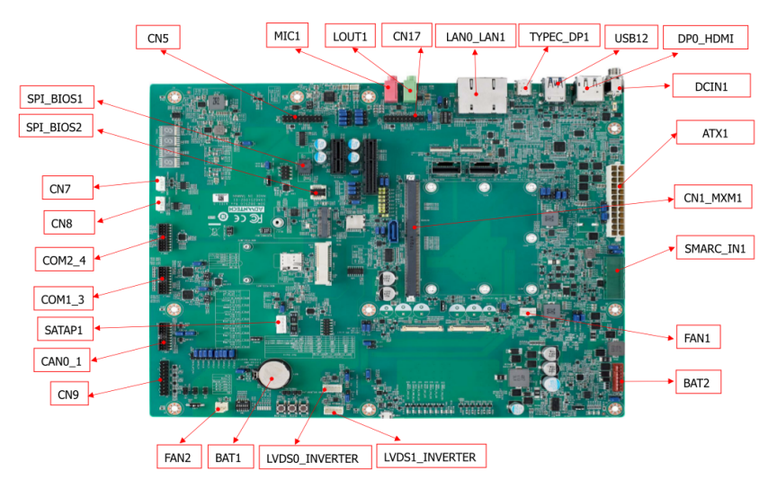
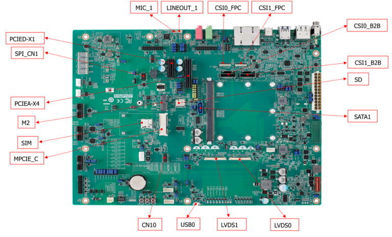
| Label | Function | Label | Function |
| ATX1 | ATX Connector | FAN1 | Smart Fan Connector |
| SMARC_IN1 | Wide Range Input Power Connector (3V~5.25V) | FAN2 | System Fan Connector |
| DCIN1 | DCIN connector | CAN0_1 | CAN Bus Connector |
| DP0_HDMI | DP & HDMI Connector | USB0 | USB OTG Connector |
| USB12 | USB 2.0 port1~2 & USB 3.0 port0 Connector | COM1_3 | COM Port Port1,3 Connector |
| TYPEC_DP1 | Type-C Connector | COM2_4 | COM Port Port2,4 Connector |
| LAN0_LAN1 | LAN0 & LAN1 Connector | CN8 | I2C connector for I2C_PM |
| LOUT1 | Line Out Connector | CN7 | I2C Connector for I2C_GP |
| MIC1 | MIC1 Connector | CN10 | eSPI Pin Header |
| CN1_MXM1 | SMARC Connector | SATAP1 | SATA Power Connector |
| PCIEA-X4 | PCIe x4 Connector | CSI0_B2B | MIPI B2B Connector for 2M Camera |
| SATA1 | SATA Port0 Connector | CSI1_B2B | MIPI B2B Connector for 8M & 13M Camera |
| PCIED-X1 | PCIe x1 Connector | SPI_BIOS1 | Carrier Board BIOS Socket (SOIC) |
| M2 | M.2 Key-E Connector | BAT1 | Coin battery holder |
| MPCIE_C | Mini PCIe Connector | BAT2 | Smart battery Connector |
| SIM | SIM card Connector | LINEOUT_1 | I2S Headphone Connector |
| LVDS1 | LVDS1 Connector | MIC_1 | I2S MIC In Connector |
| LVDS0 | LVDS0 Connector | CSI1_FPC | MIPI FPC Connector for 8M & 13M Camera |
| LVDS1_INVERTER | LVDS1 Invertor Connector | CSI0_FPC | MIPI FPC Connector for 2M Camera |
| LVDS0_INVERTER | LVDS0 Invertor Connector | CN5 | I2S2 Connector |
| SPI_BIOS2 | Carrier Board BIOS Socket (QFN) | CN17 | I2S0 Connector |
| SD | SD Card Connector |
Rear I/O
Jumper 位置( Jumper Locations)
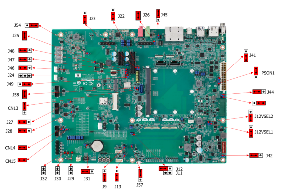
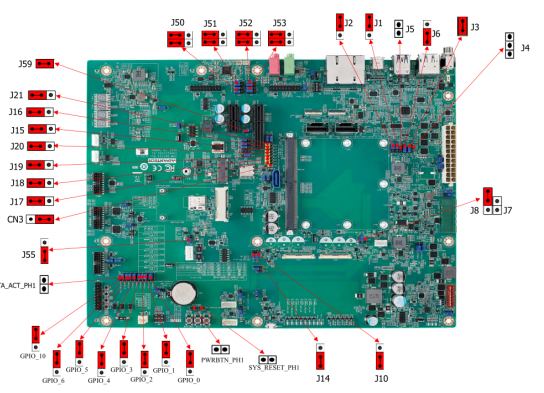
| Lable | Function | Lable | Function |
| BTN3 | Sleep Button | J14 | EDP1/LVDS1 Hot-Plug Detect Selection Header |
| BTN1 | Power Button | J56 | Standby Voltage Control Header |
| BTN2 | Reset Button | J44 | Module +3.3V/+5V Power Selection Header |
| SW4 | BOOT SELECT Switch | PSON1 | AT/ATX Selection Header |
| LID1 | LID Switch | SPI_CN1 | SPI Header |
| J30 | Enable Battery Low# Header | CN14 | For CAN Bus port0 Terminal Resistor |
| M2E_DISABLE_N1 | M.2 Wireless Disable | CN15 | For CAN Bus port1 Terminal Resistor |
| J29 | SMB Alert Enable Header | J3/J4 | DP0 EQ0 Selection |
| CN9 | Header For GPIO Test | J5/J6 | DP0 EQ1 Selection |
| J7/J8 | LVDS0 Power Selection Header | J58 | PCIE_B_CKREQ# Selection |
| J11/J12 | LVDS1 Power Selection Header | J59 | PCIE_A_CKREQ# Selection |
| J9 | LVDS0 Inverter Power Selection Heade | GPIO_0 | GPIO0/CAM0_PWR# Selection |
| J10 | EDP0/LVDS0 Hot-Plug Detect Selection Header | GPIO_1 | GPIO1/CAM1_PWR# Selection |
| J26 | HDA/I2S Selection Header | GPIO_2 | GPIO2/CAM0_RST# Selection |
| J1 | DP1/HDMI1 Select | GPIO_3 | GPIO3/CAM1_RST# Selection |
| J13 | LVDS1 Inverter Power Selection Header | GPIO_4 | GPIO4/HDA_RST# Selection |
| J31 | Clear CMOS Header | GPIO_5 | GPIO5/PWM_OUT Selection |
| J25 | SPI Power Header | GPIO_6 | GPIO6/TACHIN Selection |
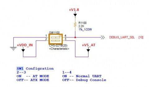
| SW1 | COM1 mode Select | SATA_ACT_PH1 | SATA act# Header |
| SW2 | COM3 mode Select | PWRBTN_PH1 | Power button Header |
| J41 | Core Power Voltage Control Header | SYS_RESET_PH1 | Reset button Header |
| J2 | DDI1 AUX/DDC Selection |
LED Function List
| Location | Function |
| MODULE_VIN_LED1 | WDT_TIME_OUT# Indicate |
| MODULE_5V_LED | Module 5V Indicate |
| MODULE_VIN_LED | Module +V_MOD_IN Indicate |
| RESET_OUT_LED | RESET_OUT Indicate |
| RESET_OUT_LED | CARRIER_STBY Indicate |
| CARRIER_PWR_ON_LED | CARRIER_PWR_ON Indicate |
| MODULE_3P3V_LED | Module 3.3V Indicate |
| 3P3V_LED | Carrier Board +V3.3 Indicate |
| 5V_LED | Carrier Board +V5 Indicate |
| 5V_DUAL_LED | Carrier Board +V5SB Indicate |
| 3P3V_DUAL_LED | Carrier Board +V3.3SB Indicate |
| 5VA_LED | Carrier Board +V5D_MOD Indicate |
| SATA_LED | SATA Indicate |
| SOM_LED | SOM BOM Indicate |
| RISC_LED | RISC BOM Indicate |
Switch Settings
- SW4 (Boot Select / Force Recovery / Test Switches)
- LID1 (LID Button Enable/Disable Switches)
- SW5 (LAN CONN LED Pull High Switches)
- SW1 (COM0 Settings)
- SW2 (COM2 Settings)
- SW3 (I2S Clock Settings)
- M2E_DISABLE_N1 (M.2 Wireless Disable Switch)
接口引脚定義 (Connector Pin definitions)
- ATX1 Pin Connector
- SMARC_IN1 Pin Connectors
- BAT1 RTC Battery Connectors
- DCIN1 DC-IN Power Connectors
- CAN0_1 CAN Bus Connectors
- CN9 GPIO Headers
- COM2_4 COM Port2&4 Connectors
- COM1_3 COM Port1&3 Connectors
- CN10 ESPI Headers
- LVDS0 LVDS Connectors
- LVDS0_INVERTER LVDS INVERTER Connectors
- LVDS1 LVDS Connectors
- LVDS1_INVERTER LVDS INVERTER Connectors
- CN7 I2C_GP Connectors
- SPI_CN1 SPI Connectors
- SATAP1 SATA PWR Connectors
- CSI0_FPC Connectors
- CSI1_FPC Connectors
- CN5 I2S2 Connectors
- CN17 I2S0 Connectors
- PWRBTN_PH1 PWRBTN Pin Headers
- SYS_RESET_PH1 SYS RESET Pin Headers
- SATA_ACT_PH1 SATA ACT# Pin Headers
- J32 Power LED Pin Headers
- J30 BATLOW Pin Headers
- J29 SMBUS Alert Pin Headers
- J41 Core Power Controls
- PSON1 ATX/AT Mode Selection
- J56 Standby Power Controls
- J44 Module Power Settings
- J7, J8 LVDS0 Power Selection
- J9 LVDS0 Inverter Power Selection
- J11, J12 LVDS1 Power Selection
- LVDS1 Inverter Power Selection
- EDP0 / LVDS0 HPD Selection
- J14 EDP1/LVDS1 HPD Selection
- CN14 CAN0 Terminal Resistor Selection
- CN15 CAN1 Terminal Resistor Selection
- J2 DDI1 AUX/DDC Selection
- J1 DP1/HDMI1 Selection
- J58 PCIE_B_CKREQ# Selection
- J59 PCIE_A_CKREQ# Selection
- J31 Clear CMOS
- J25 +V1.8M_SPI Power Jumpers
- GPIO_0 GPIO0 Settings
- GPIO_1 GPIO1 Settings
- GPIO_2 GPIO2 Settings
- GPIO_3 GPIO3 Settings
- GPIO_4 GPIO4 Settings
- GPIO_5 GPIO5 Settings
- GPIO_6 GPIO6 Settings
- J26 HDA/I2S Selection
机械尺寸 (Mechanical Characteristics)
AOM-5521
快速入门 (Quick Start)
系統下載 (OS Download)
Linux系統 (Linux OS)
Linux 燒錄方法 (Linux Flash eMMC Method)
使用Flash tool 燒錄鏡像到eMMC (Flash image into eMMC by Flash Tools)
Step0: 檢查SD卡在Linux 環境的代號 (check SD card symbol in Linux system)
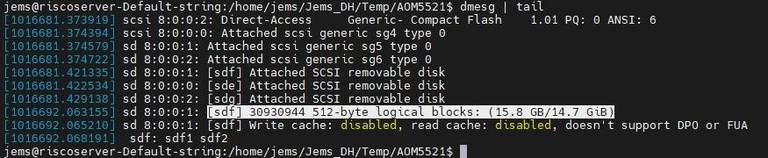
Step1: 創造一張可開機的SD 卡 (Create a bootable SD card)
Command :
$ sudo dd if=5521A1AIM38LIVG0009_iMX95_8G_2025-03-06.img of=/dev/sdf bs=1M conv=fsync status=progress

Step2: 將可開機的SD 卡插入底板SD卡卡槽(Plug the SD card into Carrier board 's SD card slot)
Step4: 確認開機選擇指撥開關
SD 卡開機模式: (2, 3:on, others off)
eMMC 開機模式: (1: on, others off)
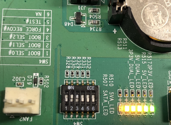
Step3:打開電源 和 終端機 (Turn on the Power & Terminal)
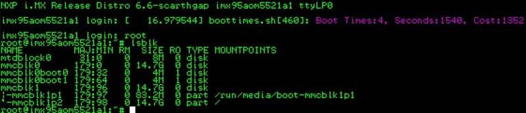
Step4: 下載flash tools image檔案,並複製到U盤中(Download and copy the flash tool image file, then copy to USB Disk), USB Disk use the exFAT file system for an example.
Step5: 將U盤連接到AOM-5521系統, 解壓縮image檔(Connect USB Disk to the AOM-5521 system, then unzip the flash tool image file)
解壓縮(Unzip/tar the file), 先設定系統時間(setup system time first), tar解壓縮加入--no-same-owner參數(tar + --no-sam-owner)
# date -s "2025-05-21 16:21:00"
# tar zxf 5521A1AIM38LIVG0009_iMX95_8G_flash_tool.tgz --no-same-owner

- 將U盤連接到AOM-5521系統, 進入flsah tool下的mk_inand資歷夾, 執行指令./mksd-linux.sh /dev/mmcblk0燒錄image到eMMC(Connect USB Disk to AOM-5521 system, browser to mk_inand folder and execute flash shell script "./mksd-linux.sh /dev/mmcblk0"
如果mk_inand資料夾下沒有mksd-linux.sh檔案, 請到以下連結下載並複製到mk_inand下(Please download the mksd-linux.sh file from the link below if there is no script file in mk_inand deiectory)
Download mksd-linux.sh in <https://github.com/ADVANTECH-Corp/RISC_tools_scripts/blob/mickledore/imx8/mksd-linux.sh>
| AOM-5521 | |
| SD card | /dev/mmcblk1 |
| eMMC | /dev/mmcblk0 |
# ./mksd-linux.sh /dev/mmcblk0
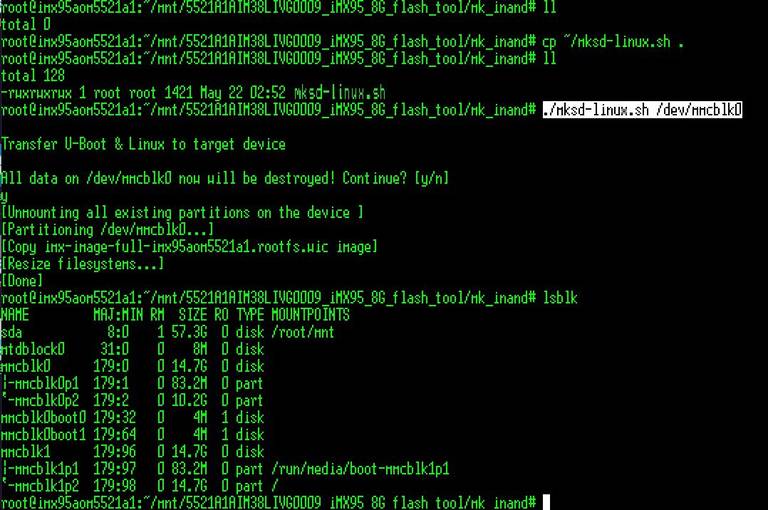
- 切換開機switch 1:on 2,3,4,5,6:off來設定成從eMMC開機(Change boot switch to "1:on 2,3,4,5,6:off" to boot from eMMC. Reboot system).
Debug 串口調試 (Debug port Setting)
Debug port output:
| AOM-5521 CPU | Linux device node | AOM-5521 golden finger | DB5901 | DB2510 |
| UART5 | /dev/ttyLP4 | SER2 | CN15B down | COM3 |
| UART1: A core | /dev/ttyLP0 | SER3 | COM3 | COM4 |
| UART6 | /dev/ttyLP5 | SER0 | CN15A up | COM1 |
| UART2: M core | SER1 | COM1 | COM2 |
以 Tera Term 为例介绍如何使用串口调试功能
   Baud Rate波特率:115200
   Data 数据位:8
   Parity 奇偶校验:无
   Stop 停止位:1
   Flow Control流控:无
Tera Term Tool
Check the Serial port in Device Manager (查看PC端的串口号):
if you can not identify the Serial device, please check your serial driver.
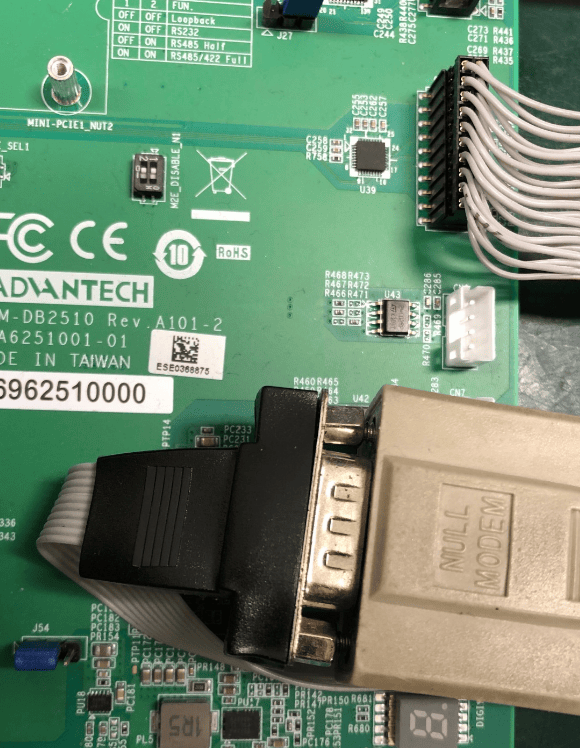
Debug port connection (串口連接)
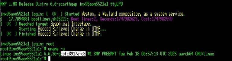
Log into Terminal Tool (进入串口调试终端):
Linux系统的基本使用(Linux System Basic Operating Method)
UUU 使用方法(USB Connection (OTG port))
Download uuu tool: Releases · nxp-imx/mfgtools
Inofrmation for uuu: Home · nxp-imx/mfgtools Wiki
Version for tested:
uuu (Universal Update Utility) for nxp imx chips -- libuuu_1.5.182-0-gda3cd53

The “imx-boot-imx95aom5521a1-8G.bin-flash_all” file is included in 5521A1AIM38LIVG0XXX_iMX95_8G_imx-boot.tgz. XXX is the version.
The "imx-image-full-imx95aom5521a1.rootfs.wic" file included in 5521A1AIM38LIVG0XXX_iMX95_8G_flash_tool/tgz.
U-Boot image: imx-boot-imx95aom5521a1-8G.bin-flash_all
Complete Image: imx-image-full-imx95aom5521a1.rootfs.wic
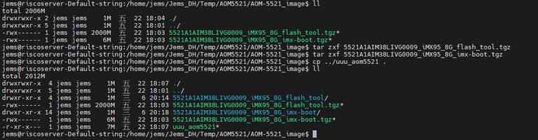
Connect USB cable to USB OTG port.
Change the boot switch to "4:on 1,2,3,5,6:off" to boot from force recovery mode.
Type the command below to flash eMMC:
$ sudo ./uuu_aom5521 -b emmc_all 5521A1AIM38LIVG0009_iMX95_8G_imx-boot/imx-boot-imx95aom5521a1-8G.bin-flash_all 5521A1AIM38LIVG0009_iMX95_8G_flash_tool/image/imx-image-full-imx95aom5521a1.rootfs.wic

Display Setting (ROM-5722)
Ex:
list dtb files in u-boot:
=> fatls mmc 0
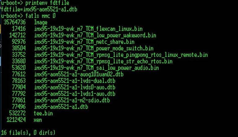
=> setenv fdtfile imx95-aom5521-a1-lvds0-auo.dtb
U-boot Command :
- Display
- HDMI (default)
- imx95-aom5521-a1.dtb
- LVDS
- g070vw01(LVDS0)
- imx95-aom5521-a1-lvds0-auo.dtb
- g070vw01(LVDS1)
- imx95-aom5521-a1-lvds1-auo.dtb
- g215hvn01(DUAL LVDS)
- imx95-aom5521-a1-lvds-dual.dtb
- g070vw01(LVDS0)
- DSI
- auog101uan02(DSI)
- imx95-aom5521-a1-auog101uan02.dtb
- auog101uan02(DSI)
- HDMI (default)
- Camera
- OV5640 (default)
- imx95-aom5521-a1.dtb
- OV5640 (default)
Audio使用方法(Audio Test Method)
Audio codec (sgtl5000): Connect ROM-EG51 to AUDIO pin header
DB-2520 has two I2S pin heaters CN5 and CN17.
Test on DB2510: CN17
J26: no jumper
SW3: 1:off, 2-on
J50~J53: pin13
Check audio codec:
# cat /proc/asound/cards
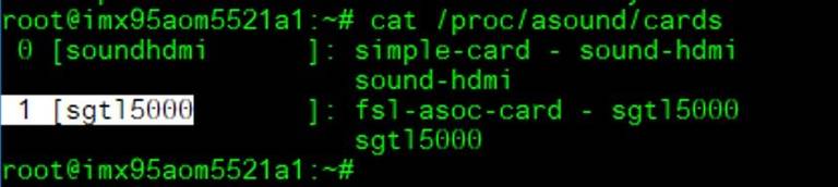
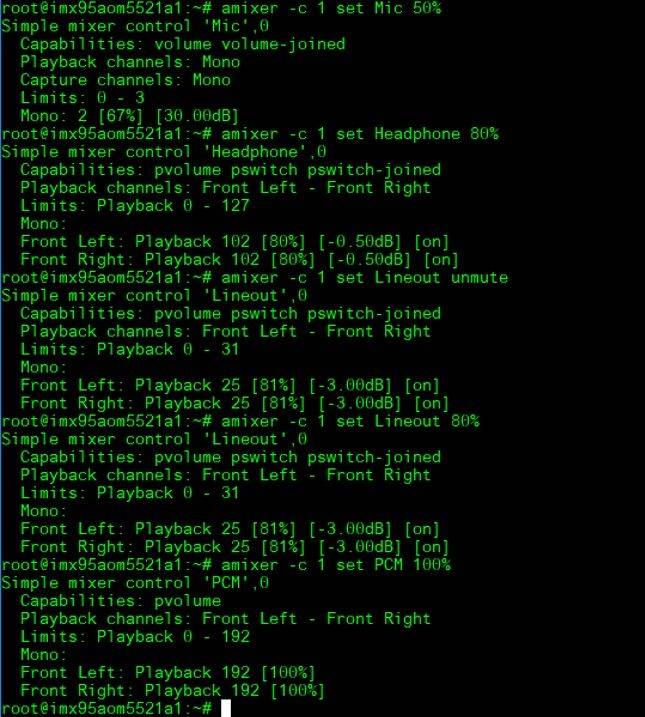
Set MIC and headphones: The sgtl5000 is card 1:
# amixer -c 1 set Mic 50%
# amixer -c 1 set Headphone 80%
# amixer -c 1 set Lineout unmute
# amixer -c 1 set Lineout 80%
# amixer -c 1 set PCM 100%
Record and playback:
# arecord –D plughw:1,0 -t wav -c 2 -r 44100 -d 10 /tmp/mic.wav

# aplay -D plughw:1,0 /tmp/mic.wav

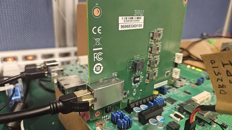
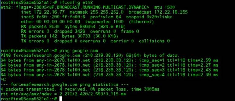
乙太網路使用方法(Ethernent Testing Method)
Command: ifconfig
Command: Ping - I eth1 8.8.8.8 or Ping - I eth0 8.8.8.8
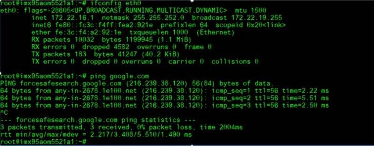
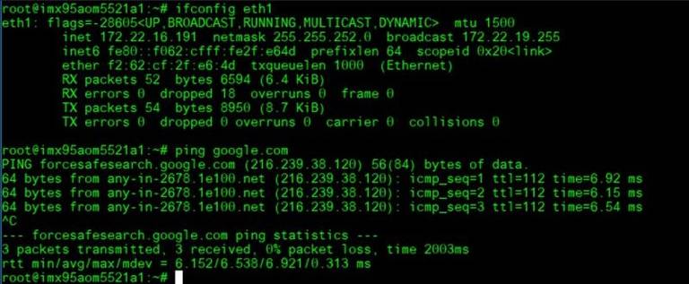
10 G:
WiFi使用方法(WIFI Testing Method)
Test with AIW-167(M.2): Switch SOM-DB2510 J15~J21 to 1 and 2.
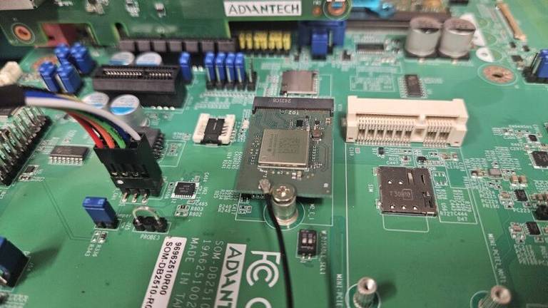
Load dtb file in u-boot:
=> setenv fdtfile imx95-aom5521-a1-m2-sdio.dtb; boot
Install Driver:
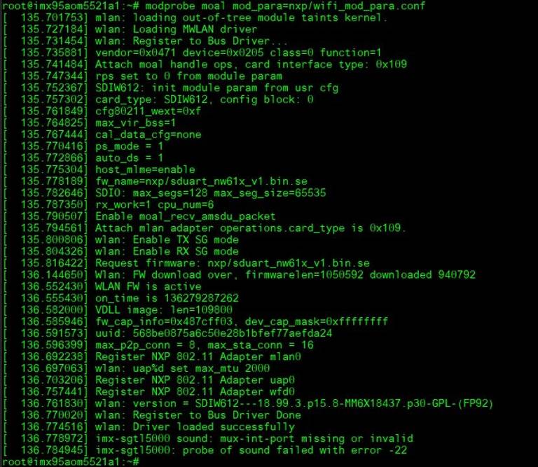
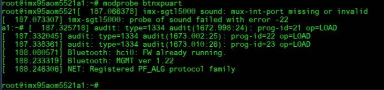
# modprobe moal mod_para=nxp/wifi_mod_para.conf
# modprobe btnxpuart
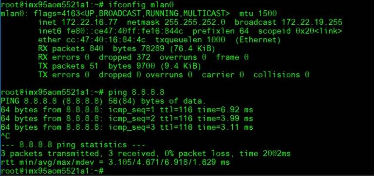
WiFi Test:
AP PW: xxxxxxxx
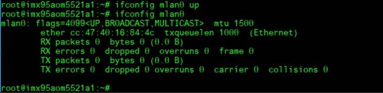
# ifconfig mlan0 up
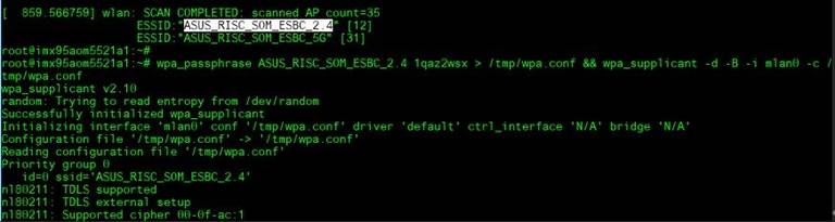
# wpa_passphrase ASUS_RISC_SOM_ESBC_2.4 xxxxxxxx > /tmp/wpa.conf && wpa_supplicant -d -B -i mlan0 -c /tmp/wpa.conf
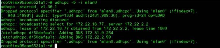
# udhcpc -b -i mlan0
# ping 8.8.8.8

藍芽使用方法(Bluetooth Operating Method)
Test AIW-167 BT: Follow the above WiFi test to install the driver and run the BT test.
BT Test:
# hciconfig hci0 up
# bluetoothctl
# discoverable on
# pairable on
# scan on


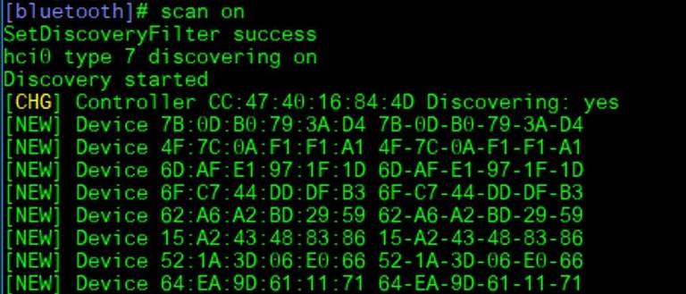
Device 84:C5:A6:D3:AF:E4 NB090726
scan off
pair 84:C5:A6:D3:AF:E4
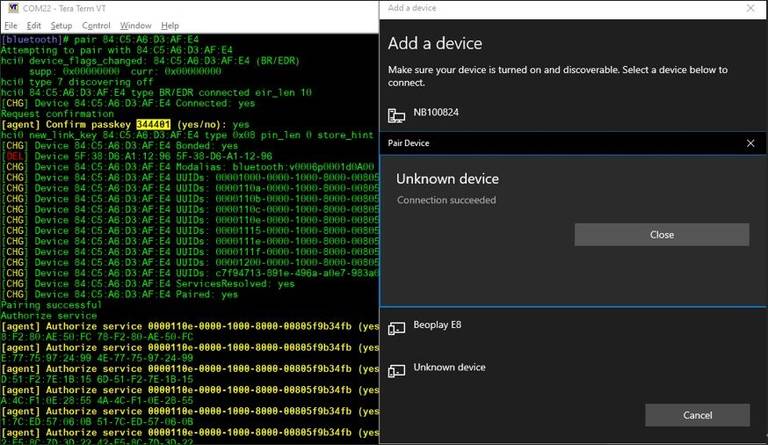
# connect 84:C5:A6:D3:AF:E4

4G使用方法(4G Testing Method)
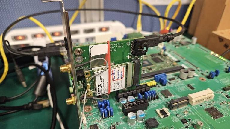
Test with AIW-344(Full-size mPCIe USB interface): Connect to PCIe x4 slot and mini USB to TypeA
Test by MBIM mode:
Enable AIW-344 module MBIM mode:
# echo -e "AT+GTUSBMODE=29\r" > /dev/ttyUSB1
# systemctl stop connman
# systemctl disable connman
(System Reboot)

Install driver and confige mbim network:
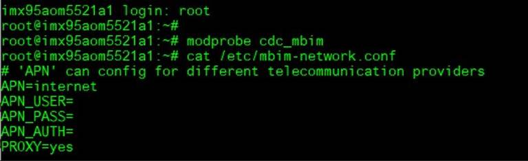
# modprobe cdc_mbim
# vi /etc/mbim-network.conf
# 'APN' can config for different telecommunication providers
APN=internet
APN_USER
APN_PASS
APN_AUTH
PROXY=yes
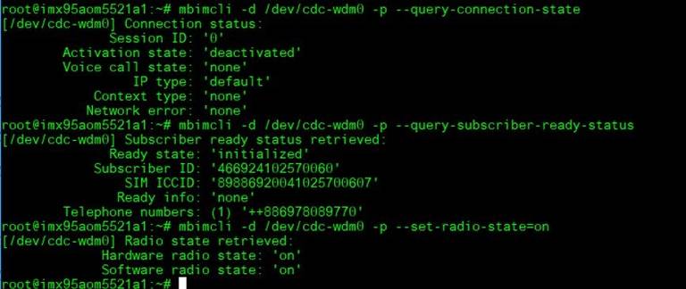
# mbimcli -d /dev/cdc-wdm0 -p --query-connection-state
# mbimcli -d /dev/cdc-wdm0 -p --query-subscriber-ready-status
# mbimcli -d /dev/cdc-wdm0 -p --set-radio-state=on
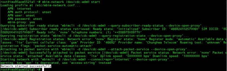
If you need to auth by PIN (If necessary): This step is not necessary
# mbimcli -d /dev/cdc-wdm0 -p --enter-pin=0000
# mbim-network /dev/cdc-wdm0 start
Query the IP addr information:
# mbimcli -d /dev/cdc-wdm0 -p --query-ip-configuration
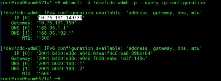
Reference the above query result for IP configuration to set up:
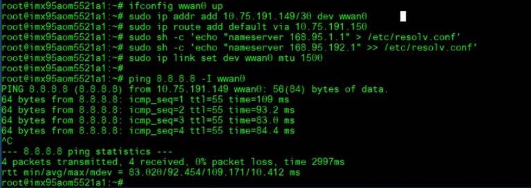
# ifconfig wwan0 up
# sudo ip addr add 10.75.191.149/30 dev wwan0
# sudo ip route add default via 10.75.191.150
# sudo sh -c 'echo "nameserver 168.95.1.1" > /etc/resolv.conf'
# sudo sh -c 'echo "nameserver 168.95.192.1" >> /etc/resolv.conf'
$ sudo ip link set dev wwan0 mtu 1500
Test Ping:
# ping 8.8.8.8 -I wwan0
GPIO使用方法(GPIO Operating Method)
GPIO pin:
| SMARC Pin# | SMARC Pin Name | CPU Ball Name | Kernel GPIO | Default Direction |
| p108 | GPIO0 | GPIO_IO12__GPIO2_IO_BIT12 | 524 | |
| p109 | GPIO1 | SD3_CLK__GPIO3_IO_BIT20 | GPIO1_CAM1_PWR# | |
| p110 | GPIO2 | SD3_CMD__GPIO3_IO_BIT21 | 565 | |
| p111 | GPIO3 | SD3_DATA0__GPIO3_IO_BIT22 | GPIO3_CAM1_RST# | |
| p112 | GPIO4 | SD3_DATA1__GPIO3_IO_BIT23 | 567 | |
| p113 | GPIO5 | GPIO_IO16__GPIO2_IO_BIT16 | 528 | |
| p114 | GPIO6 | SD3_DATA2__GPIO3_IO_BIT24 | 568 | |
| p115 | GPIO7 | SD3_DATA3__GPIO3_IO_BIT25 | 569 | |
| p116 | GPIO8 | PCA6416_P0_5 | 653 | |
| p117 | GPIO9 | PCA6416_P0_4 | 652 | |
| p118 | GPIO10 | PCA6416_P0_3 | 651 | |
| p119 | GPIO11 | PCA6416_P0_2 | 650 | |
| s142 | GPIO12 | PCA6416_P0_1 | 649 | |
| s123 | GPIO13 | PCA6416_P0_0 | 648 |
Loop-back Test (Take GPIO0 and GPIO2 as examples)

Step 1: Connect GPIO0 and GPIO2, change GPIO_0 and GPIO_2 to pin 12
Step 2: Export GPIO interface

root@imx95aom5521a1: ~# echo 524 > /sys/class/gpio/export
root@imx95aom5521a1: ~# echo 565 > /sys/class/gpio/export

Step 3: Set direction

root@imx95aom5521a1: ~# echo out > /sys/class/gpio/gpio1/direction
root@imx95aom5521a1: ~# echo in > /sys/class/gpio/gpio2/direction

Step 4: Read value and set output value then check

root@imx95aom5521a1: ~# cat /sys/class/gpio/gpio2/value
0
root@imx95aom5521a1: ~# echo 1 > /sys/class/gpio/gpio1/value
root@imx95aom5521a1: ~# cat /sys/class/gpio/gpio2/value
1
Watch Dog測試方法(Watch Dog Test Method)
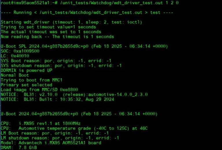
System will reboot after 3 sec:
# /unit_tests/Watchdog/wdt_driver_test.out 1 2 0
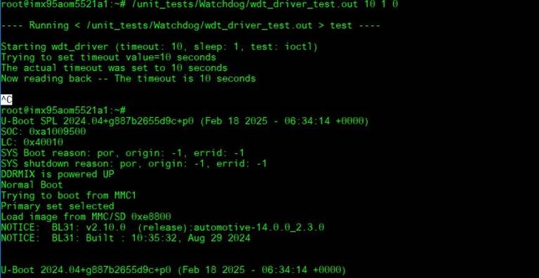
Timeout 10s:
System will not reboot. Watchdog can be refreshed when feed dog before it timeout.
# /unit_tests/Watchdog/wdt_driver_test.out 10 1 0
- Ctrl + C ==> System will reboot after 10 sec. Watchdog does not refresh after it timeout.
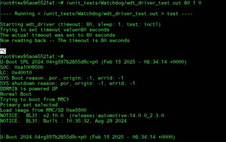
Timeout 60s:
System will not reboot. Watchdog can be refreshed when feed dog before it timeout.
# /unit_tests/Watchdog/wdt_driver_test.out 60 1 0
- Ctrl + C ==> System will reboot after 10 sec. Watchdog does not refresh after it timeout.
串口使用方法(Serial Port Operating Method)
| AOM-5521 CPU | Linux device node | AOM-5521 golden finger | DB5901 | DB2510 |
| UART5 | /dev/ttyLP4 | SER2 | CN15B down | COM3 |
| UART1: A core | /dev/ttyLP0 | SER3 | COM3 | COM4 |
| UART6 | /dev/ttyLP5 | SER0 | CN15A up | COM1 |
| UART2: M core | SER1 | COM1 | COM2 |
RS-232 Test
CN15上(SER0/UART6): /dev/ttyLP5
CN15下(SER2/UART5): /dev/ttyLP4
DB2510 COM4 (A core debug/SER3/UART1): /dev/ttyLP0
DB2510 COM1 (M core debug/SER1/UART2):
SW7 Setting (SW7設置)
MODE1 MODE0
0 0 LOOPBACK
0 1 RS232
1 0 RS485
1 1 RS422
Loopback test (eg. ttymxc0)
Connect loopback test tool
- stty ‐F /dev/ttyLP4 115200
stty ‐F /dev/ttyLP4 ‐echo
cat /dev/ttyLP4 &
echo test > /dev/ttyLP4
I2C測試方法(I2C Test Method)
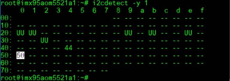
I2C test: Check I2C device
(0x50 EEPROM on module)
# i2cdetect -y 1
Write/Read/Verify eeprom Hi/Low byte
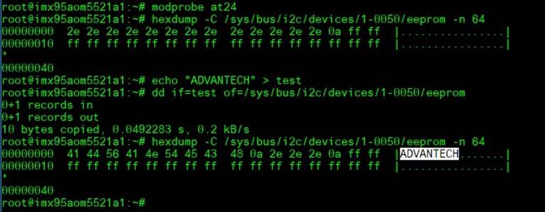
# modprobe at24
# echo "ADVANTECH" > test
# dd if=test of=/sys/bus/i2c/devices/1-0050/eeprom
# hexdump -C /sys/bus/i2c/devices/1-0050/eeprom -n 64
RTC測試方法(RTC Test Method)
Disable RTC sync service:
# systemctl stop systemd-timesyncd
# systemctl disable systemd-timesyncd

Set system time to current, then write to RTC:
# date 021710452022 && hwclock -w && date

Set one incorrect time, then read time from RTC to verify:
# date 010100002000 && hwclock -r && date

Set the system time from the RTC:
# hwclock -s && date

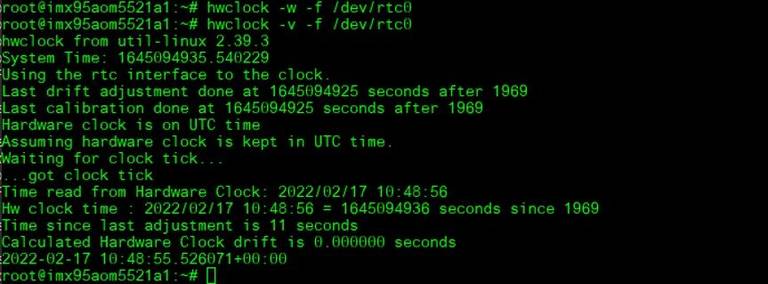
Store into RTC and check RTC current status:
# hwclock -w -f /dev/rtc0
# hwclock -v -f /dev/rtc0
Enable RTC sync service:
# systemctl enable systemd-timesyncd
# systemctl start systemd-timesyncd

TPM使用方法(TPM Test Method)
Generate Random code
# tpm2_getrandom --hex 20

Crypt msg.dat file
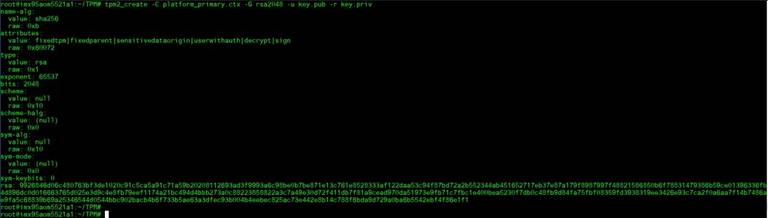
# tpm2_createprimary -C p -c platform_primary.ctx
# tpm2_create -C platform_primary.ctx -G rsa2048 -u key.pub -r key.priv
# tpm2_load -C platform_primary.ctx -u key.pub -r key.priv -c key.ctx
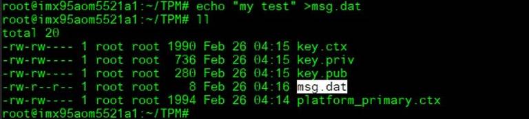
# echo "my test" >msg.dat
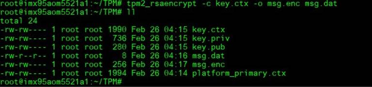
# tpm2_rsaencrypt -c key.ctx -o msg.enc msg.dat
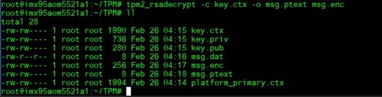
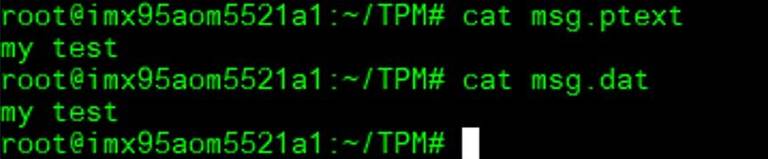
# tpm2_rsadecrypt -c key.ctx -o msg.ptext msg.enc
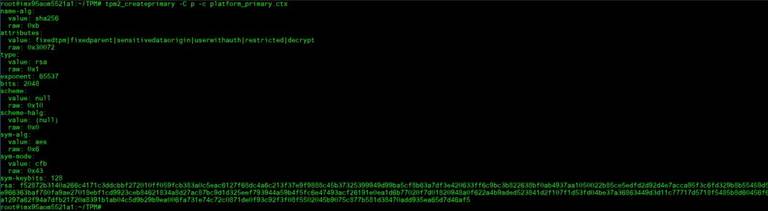

# cat msg.ptext
# cat msg.dat
Store data to TPM
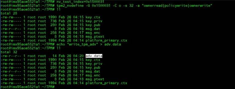
# nv_test_index=0x1500031
# tpm2_nvdefine -Q 0x1500031 -C o -s 32 -a "ownerread|policywrite|ownerwrite"
# echo "write_tpm_adv" > adv.data
# tpm2_nvwrite -Q 0x1500031 -C o -i adv.data
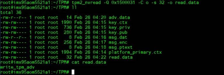
# tpm2_nvread -Q 0x1500031 -C o -s 32 -o read.data
# cat read.data
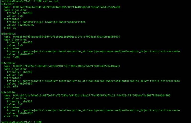
Check TPM store area
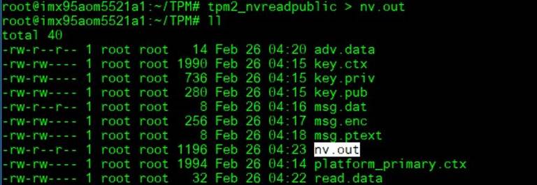
# tpm2_nvreadpublic > nv.out
# cat nv.out
SPI BUS功能測試(SPI BUS Function Test)
Storage information:
eMMC: /dev/mmcblk0
SD: /dev/mmcblk1
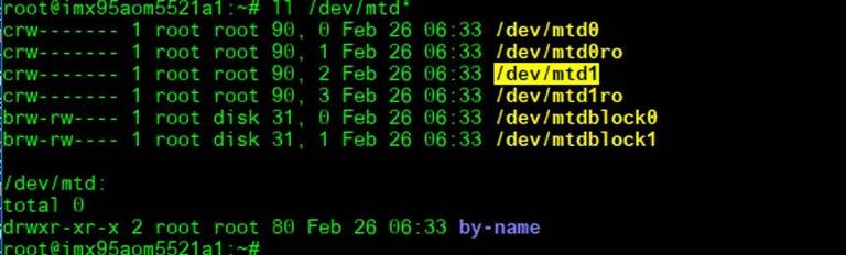
QSPI1: /dev/mtd0
SPI0_0: /dev/mtd1
SPI0_1: /dev/mtd2
SPI1_0: /dev/mtd3
SPI1_1: /dev/mtd4
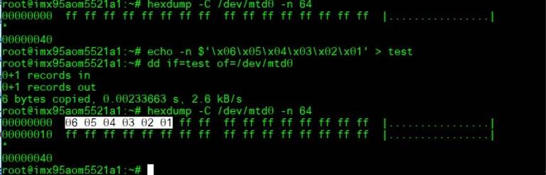
QSPIA (On the SMARC module)
# echo -n $'\x06\x05\x04\x03\x02\x01' > test
# dd if=test of=/dev/mtd0
# hexdump -C /dev/mtd0 -n 64
SPI0 test: flash (Winboan 25q64) function:
Place SPI flash to SPI_BIOS1:
J46, J47, J48: pin12
J24: pin 12
(/dev/mtd1)
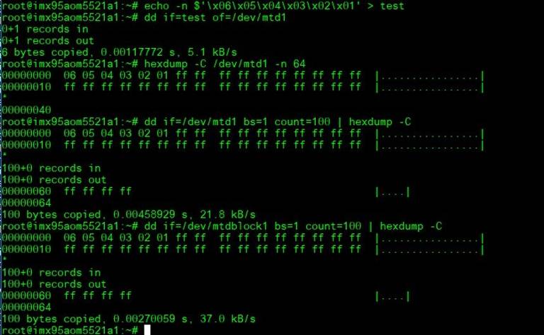
Dump SPI content:
# echo -n $'\x06\x05\x04\x03\x02\x01' > test
# dd if=test of=/dev/mtd1
# hexdump -C /dev/mtd1 -n 64
SPI1(ESPI)(CN10) test: flash (Winboan 25q64) function:
(/dev/mtd2)
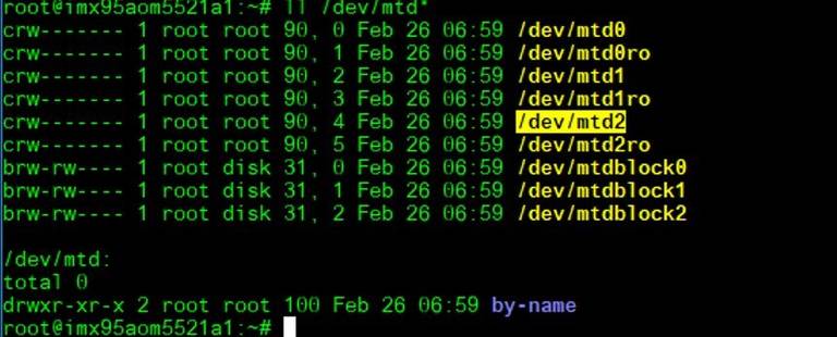
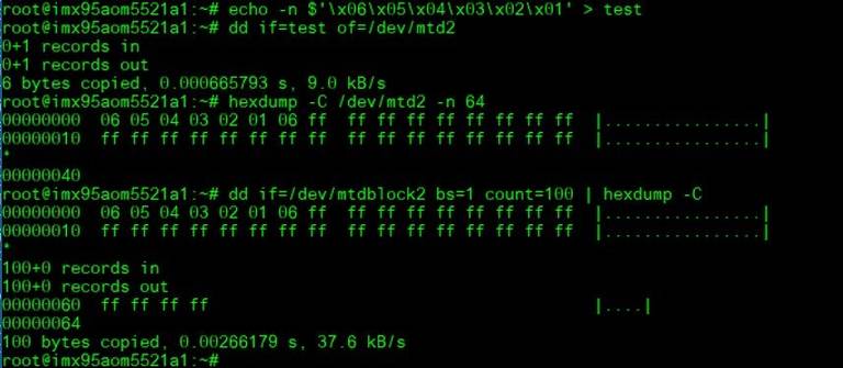
Dump SPI content:
# echo -n $'\x06\x05\x04\x03\x02\x01' > test
# dd if=test of=/dev/mtd2
# hexdump -C /dev/mtd2 -n 64
or
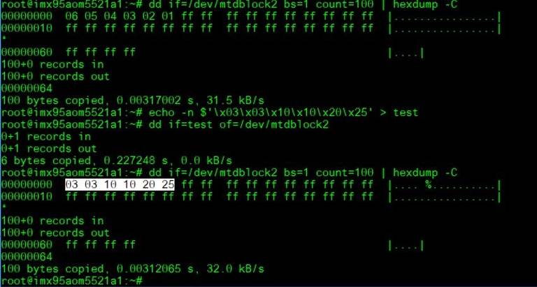
# dd if=/dev/mtdblock2 bs=1 count=100 | hexdump -C
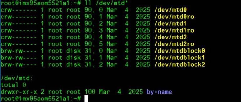
SPI_CN1: Test with ROM-EG70
(Need to rework U62 +V_SPI to +V3.3 for ROM-EG70)
(There are two SPI NOR flash on ROM-EG70)
Dump SPI content:
# echo -n $'\x03\x03\x10\x10\x20\x25' > test
# dd if=test of=/dev/mtdblock1
# hexdump -C /dev/mtd1 -n 64
or
# dd if=/dev/mtdblock1 bs=1 count=100 | hexdump –C
mtdblock1:
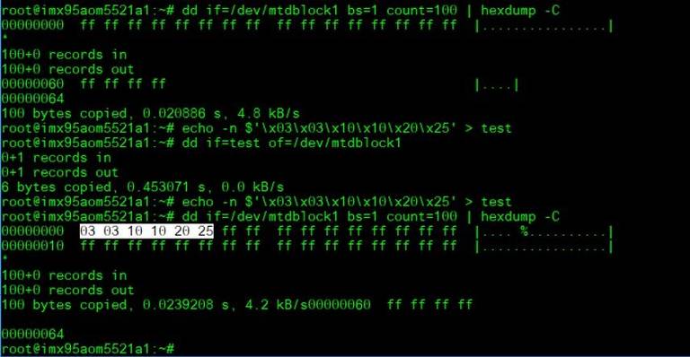
mtdblock2:
CANBUS功能測試(CABBUS Test Method)
Connect: CAN0_R_D- to CAN1_R_D- and CAN0_R_D+ to CAN1_R_D+
CAN0_R_D-: pin3
CAN0_R_D+: pin4
CAN1_R_D-: ping13
CAN1_R_D+: ping14
Set can0 and can1 up:
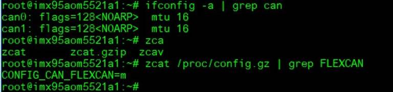
Check CAN driver
# zcat /proc/config.gz | grep FLEXCAN
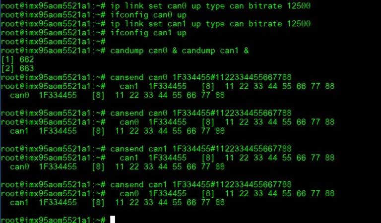
# ip link set can0 up type can bitrate 12500
# ifconfig can0 up
# ip link set can1 up type can bitrate 12500
# ifconfig can1 up
(candump can0/1)(cansend can0/1)
# candump can0 & candump can1 &
# cansend can0 1F334455#1122334455667788
# cansend can1 1F334455#1122334455667788
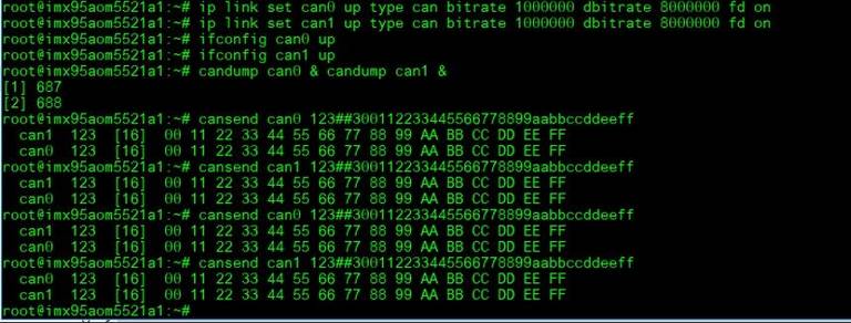
CAN FD:
# ip link set can0 up type can bitrate 1000000 dbitrate 8000000 fd on
# ip link set can1 up type can bitrate 1000000 dbitrate 8000000 fd on
# ifconfig can0 up
# ifconfig can1 up
# candump can0 & candump can1 &
# cansend can0 123##300112233445566778899aabbccddeeff
# cansend can1 123##300112233445566778899aabbccddeeff
MIPI CS功能測試(MIPI CSI Test Method)
AOM-5521 to DB-2510
CSI1: CSI1_FPC(4 lane)
CSI2: CSI0_FPC(2 lane): Not support
Preview(CSI1_FPC):
Connect OV5640 camera to EG-55 CAM2
Connect EG-55 to DB-2510 CSI1_FPC(video0)
OV5640 setup:
# media-ctl -l "'ov5640 2-003c':0 ->'csidev-4ad30000.csi':0 [1]"
# media-ctl -V "'ov5640 2-003c':0 [fmt: UYVY8_1X16/1920x1080 field:none]"
# media-ctl -V "'csidev-4ad30000.csi':0 [fmt: UYVY8_1X16/1920x1080 field:none]"
# media-ctl -V "'crossbar':2 [fmt: UYVY8_1X16/1920x1080 field:none]"
# media-ctl -V "'mxc_isi.0':0 [fmt: UYVY8_1X16/1920x1080 field:none]"
# media-ctl -V "'mxc_isi.2':0 [fmt: UYVY8_1X16/1920x1080 field:none]"
# media-ctl -V "'mxc_isi.3':0 [fmt: UYVY8_1X16/1920x1080 field:none]"
# media-ctl -V "'mxc_isi.4':0 [fmt: UYVY8_1X16/1920x1080 field:none]"
# media-ctl -V "'mxc_isi.5':0 [fmt: UYVY8_1X16/1920x1080 field:none]"
# media-ctl -V "'mxc_isi.6':0 [fmt: UYVY8_1X16/1920x1080 field:none]"
# media-ctl -V "'mxc_isi.7':0 [fmt: UYVY8_1X16/1920x1080 field:none]"
OV5640 Preview:
# gst-launch-1.0 v4l2src device=/dev/video0 ! 'video/x-raw,width=1920,height=1080' ! autovideosink
(Check the HDMI can preview the image)
遠程訪問及文件傳輸(Remote Access and File Transimmion)
**查看主板IP位址 ( Chech IP Address ):**
Command: ifconfig
Windows下SSH访问及文件传输
SSH Remote Log into Device
- SSH远程登录,以putty选择putty.exe(或者使用Xshell、SecureCRT等类似软件)
- 需要设置远程设备的IP、通讯端口(默认22)、通讯方式,登录后验证用户名密码

通用方法(General Method)
查看CPU温度(Check CPU Temperature)
    # cat /sys/devices/virtual/thermal/thermal_zone*/temp

    # 或者直接以度爲單位顯示 echo $[$(cat /sys/class/thermal/thermal_zone0/temp)/1000]° >>> 45°
查看CPU频率(Check CPU Frequency)
           # cat /sys/devices/system/cpu/cpu*/cpufreq/cpuinfo_cur_freq
           >> 500000
           # cat /sys/devices/system/cpu/cpu*/cpufreq/cpuinfo_max_freq
           >> 1800000
查看内存容量(Check Memory Capacity)
root@imx95aom5521a1:~# free -h
               total        used        free      shared  buff/cache   available
Mem:           7.5Gi       431Mi       7.1Gi        13Mi       151Mi       7.1Gi
Swap:             0B          0B          0B
root@imx95aom5521a1:~#
查看存储容量(Check Storage Capacity)
root@imx95aom5521a1:~# df -hT
Filesystem     Type      Size  Used Avail Use% Mounted on
/dev/root      ext4       15G  5.4G  8.0G  41% /
devtmpfs       devtmpfs  3.3G  4.0K  3.3G   1% /dev
tmpfs          tmpfs     3.8G     0  3.8G   0% /dev/shm
tmpfs          tmpfs     1.6G   11M  1.5G   1% /run
tmpfs          tmpfs     3.8G   12K  3.8G   1% /tmp
tmpfs          tmpfs     3.8G  260K  3.8G   1% /var/volatile
/dev/mmcblk0p1 vfat       84M   37M   47M  45% /run/media/boot-mmcblk0p1
/dev/mmcblk1p1 vfat       84M   37M   47M  45% /run/media/boot-mmcblk1p1
tmpfs          tmpfs     769M  8.0K  769M   1% /run/user/0
/dev/mmcblk1p2 ext4       15G  5.4G  8.1G  41% /run/media/root-mmcblk1p2
root@imx95aom5521a1:~#
網路Ping測試(Ping Network Testing)
     ping 8.8.8.8
     PING 8.8.8.8 (8.8.8.8) 56(84) bytes of data.
     64 bytes from 8.8.8.8: icmp_seq=1 ttl=54 time=2.10 ms
     64 bytes from 8.8.8.8: icmp_seq=2 ttl=54 time=2.10 ms
設置RTC (RTC Setting)
root@imx8mprom5722a1:~# systemctl stop ntpdate.service
root@imx8mprom5722a1:~# date 090816072021 && hwclock -w && date
Wed Sep  8 16:07:00 UTC 2021
Tue Nov 23 07:38:50 UTC 2021
root@imx8mprom5722a1:~# date
Tue Nov 23 07:38:56 UTC 2021
root@imx8mprom5722a1:~#
Add Patch in linux-imx_6.1.bb file
SRC_URI:append:imx8qmrom5722a1 += " file://panel_gpi4.patch"
Linux BSP編譯方法(Linux BSP Compile Method)
完整的 BSP 編譯步驟請參考對應 OS 版本的 README:
Build known issue
如果有驗證上的錯誤 請使用以下的方法
### repo sync failed with Server certificate verification failed. CAfile: /etc/ssl/certs/ca-certificates.crt CRLfile: none ERROR: gstreamer1.0-1.14.4.imx-r0 do_unpack: Fetcher failure: Fetch command export PSEUDO_DISABLED=1; export PATH="/hom e/adv/adv-release-bsp/build_x11/tmp/work/aarch64-poky-linux/gstreamer1.0/1.14.4.imx-r0/recipe-sysroot-native/usr/bin/py thon3-native:/home/adv/adv-release-bsp/sources/poky/scripts:/home/adv/adv-release-bsp/build_x11/tmp/work/aarch64-poky-l inux/gstreamer1.0/1.14.4.imx-r0/recipe-sysroot-native/usr/bin/aarch64-poky-linux:/home/adv/adv-release-bsp/build_x11/tm p/work/aarch64-poky-linux/gstreamer1.0/1.14.4.imx-r0/recipe-sysroot/usr/bin/crossscripts:/home/adv/adv-release-bsp/buil d_x11/tmp/work/aarch64-poky-linux/gstreamer1.0/1.14.4.imx-r0/recipe-sysroot-native/usr/sbin:/home/adv/adv-release-bsp/b uild_x11/tmp/work/aarch64-poky-linux/gstreamer1.0/1.14.4.imx-r0/recipe-sysroot-native/usr/bin:/home/adv/adv-release-bsp /build_x11/tmp/work/aarch64-poky-linux/gstreamer1.0/1.14.4.imx-r0/recipe-sysroot-native/sbin:/home/adv/adv-release-bsp/ build_x11/tmp/work/aarch64-poky-linux/gstreamer1.0/1.14.4.imx-r0/recipe-sysroot-native/bin:/home/adv/adv-release-bsp/so urces/poky/bitbake/bin:/home/adv/adv-release-bsp/build_x11/tmp/hosttools"; export HOME="/home/adv"; git -c core.fsyncob jectfiles=0 submodule update --init --recursive failed with exit code 1, output:
Submodule 'common' (
<https://anongit.freedesktop.org/git/gstreamer/common.git)> registered for path 'common'
Cloning into '/home/adv/adv-release-bsp/build_x11/tmp/work/aarch64-poky-linux/gstreamer1.0/1.14.4.imx-r0/git/common'...
fatal: unable to access '
<https://anongit.freedesktop.org/git/gstreamer/common.git/':> server certificate verification fa iled. CAfile: /etc/ssl/certs/ca-certificates.crt CRLfile: none
fatal: clone of '
<https://anongit.freedesktop.org/git/gstreamer/common.git'> into submodule path '/home/adv/adv-release-b sp/build_x11/tmp/work/aarch64-poky-linux/gstreamer1.0/1.14.4.imx-r0/git/common' failed
Failed to clone 'common'. Retry scheduled
Cloning into '/home/adv/adv-release-bsp/build_x11/tmp/work/aarch64-poky-linux/gstreamer1.0/1.14.4.imx-r0/git/common'...
fatal: unable to access '
<https://anongit.freedesktop.org/git/gstreamer/common.git/':> server certificate verification fa iled. CAfile: /etc/ssl/certs/ca-certificates.crt CRLfile: none
fatal: clone of '
<https://anongit.freedesktop.org/git/gstreamer/common.git'> into submodule path '/home/adv/adv-release-b sp/build_x11/tmp/work/aarch64-poky-linux/gstreamer1.0/1.14.4.imx-r0/git/common' failed
Failed to clone 'common' a second time, aborting
ERROR: gstreamer1.0-1.14.4.imx-r0 do_unpack: Function failed: base_do_unpack
ERROR: Logfile of failure stored in: /home/adv/adv-release-bsp/build_x11/tmp/work/aarch64-poky-linux/gstreamer1.0/1.14. 4.imx-r0/temp/log.do_unpack.42631
ERROR: Task (/home/adv/adv-release-bsp/sources/meta-fsl-bsp-release/imx/meta-bsp/recipes-multimedia/gstreamer/gstreamer 1.0_1.14.imx.bb:do_unpack) failed with exit code '1'
ERROR: gstreamer1.0-plugins-base-1.14.4.imx-r0 do_unpack: Fetcher failure: Fetch command export PSEUDO_DISABLED=1; expo rt PATH="/home/adv/adv-release-bsp/build_x11/tmp/work/aarch64-mx8mm-poky-linux/gstreamer1.0-plugins-base/1.14.4.imx-r0/ recipe-sysroot-native/usr/bin/python3-native:/home/adv/adv-release-bsp/sources/poky/scripts:/home/adv/adv-release-bsp/b uild_x11/tmp/work/aarch64-mx8mm-poky-linux/gstreamer1.0-plugins-base/1.14.4.imx-r0/recipe-sysroot-native/usr/bin/aarch6 4-poky-linux:/home/adv/adv-release-bsp/build_x11/tmp/work/aarch64-mx8mm-poky-linux/gstreamer1.0-plugins-base/1.14.4.imx -r0/recipe-sysroot/usr/bin/crossscripts:/home/adv/adv-release-bsp/build_x11/tmp/work/aarch64-mx8mm-poky-linux/gstreamer 1.0-plugins-base/1.14.4.imx-r0/recipe-sysroot-native/usr/sbin:/home/adv/adv-release-bsp/build_x11/tmp/work/aarch64-mx8m m-poky-linux/gstreamer1.0-plugins-base/1.14.4.imx-r0/recipe-sysroot-native/usr/bin:/home/adv/adv-release-bsp/build_x11/ tmp/work/aarch64-mx8mm-poky-linux/gstreamer1.0-plugins-base/1.14.4.imx-r0/recipe-sysroot-native/sbin:/home/adv/adv-rele ase-bsp/build_x11/tmp/work/aarch64-mx8mm-poky-linux/gstreamer1.0-plugins-base/1.14.4.imx-r0/recipe-sysroot-native/bin:/ home/adv/adv-release-bsp/sources/poky/bitbake/bin:/home/adv/adv-release-bsp/build_x11/tmp/hosttools"; export HOME="/hom e/adv"; git -c core.fsyncobjectfiles=0 submodule update --init --recursive failed with exit code 1, output:
Submodule 'common' (
<https://anongit.freedesktop.org/git/gstreamer/common.git)> registered for path 'common'
Cloning into '/home/adv/adv-release-bsp/build_x11/tmp/work/aarch64-mx8mm-poky-linux/gstreamer1.0-plugins-base/1.14.4.im x-r0/git/common'...
fatal: unable to access '
<https://anongit.freedesktop.org/git/gstreamer/common.git/':> server certificate verification fa iled. CAfile: /etc/ssl/certs/ca-certificates.crt CRLfile: none
fatal: clone of '
<https://anongit.freedesktop.org/git/gstreamer/common.git'> into submodule path '/home/adv/adv-release-b sp/build_x11/tmp/work/aarch64-mx8mm-poky-linux/gstreamer1.0-plugins-base/1.14.4.imx-r0/git/common' failed
Failed to clone 'common'. Retry scheduled
Cloning into '/home/adv/adv-release-bsp/build_x11/tmp/work/aarch64-mx8mm-poky-linux/gstreamer1.0-plugins-base/1.14.4.im x-r0/git/common'...
fatal: unable to access '
<https://anongit.freedesktop.org/git/gstreamer/common.git/':> server certificate verification fa iled. CAfile: /etc/ssl/certs/ca-certificates.crt CRLfile: none
fatal: clone of '
<https://anongit.freedesktop.org/git/gstreamer/common.git'> into submodule path '/home/adv/adv-release-b sp/build_x11/tmp/work/aarch64-mx8mm-poky-linux/gstreamer1.0-plugins-base/1.14.4.imx-r0/git/common' failed
Failed to clone 'common' a second time, aborting
ERROR: gstreamer1.0-plugins-base-1.14.4.imx-r0 do_unpack: Function failed: base_do_unpack
ERROR: Logfile of failure stored in: /home/adv/adv-release-bsp/build_x11/tmp/work/aarch64-mx8mm-poky-linux/gstreamer1.0 -plugins-base/1.14.4.imx-r0/temp/log.do_unpack.51633
ERROR: Task (/home/adv/adv-release-bsp/sources/meta-fsl-bsp-release/imx/meta-bsp/recipes-multimedia/gstreamer/gstreamer 1.0-plugins-base_1.14.imx.bb:do_unpack) failed with exit code '1'
nnshark error
<https://community.nxp.com/t5/i-MX-Processors/Yocto-3-3-5-10-72-BSP-Build-Fail/m-p/1487902>