AFE-R761 DI/DO
Contents
- 1Hardware pin definition:
- 2SW Function 2.1Export GPIO 2.2Set GPIO direction to in/out 2.3Set GPIO value 0/1 if GPIO pin define is output 2.4Unexport GPIO
- 3Export DO0 and DI1 3.1Set DO1 to output and DI1 to input 3.2Change DO0 to 1 and read DI1 value 3.3Digital Input 3.4Show DI/DO ports 3.5Get DI Status
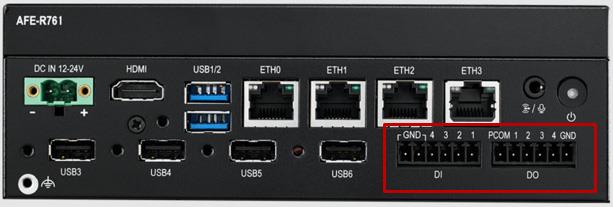
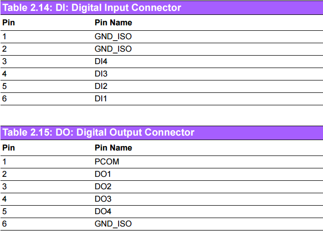
Hardware pin definition:
AFE-R761 supports 4x digital inputs and 4x digital outputs.
| DI,DO Ports |
|---|
| GPIO Number |
| DI1 |
| DI2 |
| DI3 |
| DI4 |
| DO1 |
| DO2 |
| DO3 |
| DO4 |
Note: The DI GPIO port can only be used for input, and the DO GPIO port can only be used for output. Do not echo "out" on the DI port or echo "out" on the DI port.
SW Function
Export GPIO then you can use control GPIO from user space through sysfs.
Export GPIO
# echo 505 > /sys/class/gpio/export
Set GPIO direction to in/out
# echo "out" > /sys/class/gpio/gpio505/direction
Set GPIO value 0/1 if GPIO pin define is output
# echo 1 > /sys/class/gpio/gpio505/value
Unexport GPIO
# echo 505 > /sys/class/gpio/unexport
DO1 and DI1 are taken as an example: Connect DO0 and DI1
Export DO0 and DI1
# echo 505 > /sys/class/gpio/export
# echo 501 > /sys/class/gpio/export
Set DO1 to output and DI1 to input
# echo "out" > /sys/class/gpio/gpio505/direction
# echo "in" > /sys/class/gpio/gpio501/direction
Change DO0 to 1 and read DI1 value
# echo 1 > /sys/class/gpio/gpio505/value
# cat /sys/class/gpio/gpio501/value
1
Digital Input
4 x DI w 2500VDC isolation protection (terminal block) - Wet contact: Logic: 03VDC(max);Logic 1: 1030VDC - Dry contact: Logic 0: Shorted to GND; Logic 1: Open (Default) Digital Output
4 x DO w 2500VDC isolation protection (terminal block) - Output voltage: 5-30VDC - Output capability Sink(NPN): 500mA per channel
Show DI/DO ports
# #---- Show DI ports ----# #
# cd /dev/
# ls DI*
DI1 DI2 DI3 DI4

# #---- Show DO ports ----# #
# cd /dev/
# ls DO*
DO1 DO2 DO3 DO4
Get DI Status
Take DI1 for example
# cat /dev/DI1
1
Set and Get DO Status
Take DO1 for example:(The DO interface of UIO-4033 is of sink type,Default state: No output)
# #---- Set 0 to DO1 ----# #
# echo 0 > /dev/DO1

# #---- Set 1 to DO1 ----# #
# echo 1 > /dev/DO1

# #---- Get DO1 status ----# #
# cat /dev/DO1
1
Note:
Setting 0 to make the external circuit NOT conductive. Setting 1 to make the external circuit conductive.
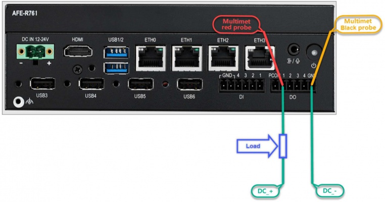
The wiring and measurement methods can be referred to as shown in the following diagram.
Note:
1、There are no specific requirements for the power supply. Just make sure it is within the product POR specification of 5 to 30V DC (and ensure that the overshoot at the moment of power-on does not exceed 30V of the POR). Please be sure to confirm the overshoot at power-on of the POWER Supply being used.
2、When echo is "0", the DO on the UIO is open mode and the level state is high.
3、When echo is "1", the DO on the UIO is closed mode and the level is low.